20 AMP REGULATED ALTERNATOR
The 20 amp regulated alternator system provides AC current through
two output leads to the regulator-rectifier. The regulator-rectifier con-
verts the AC current to DC, and regulates the current to the battery.
The charging rate will vary with engine RPM and temperature.
The stator, regulator-rectifier and flywheel are NOT interchangeable
with any other alternator system.
When checking the alternator components, make the tests in the
following sequence:
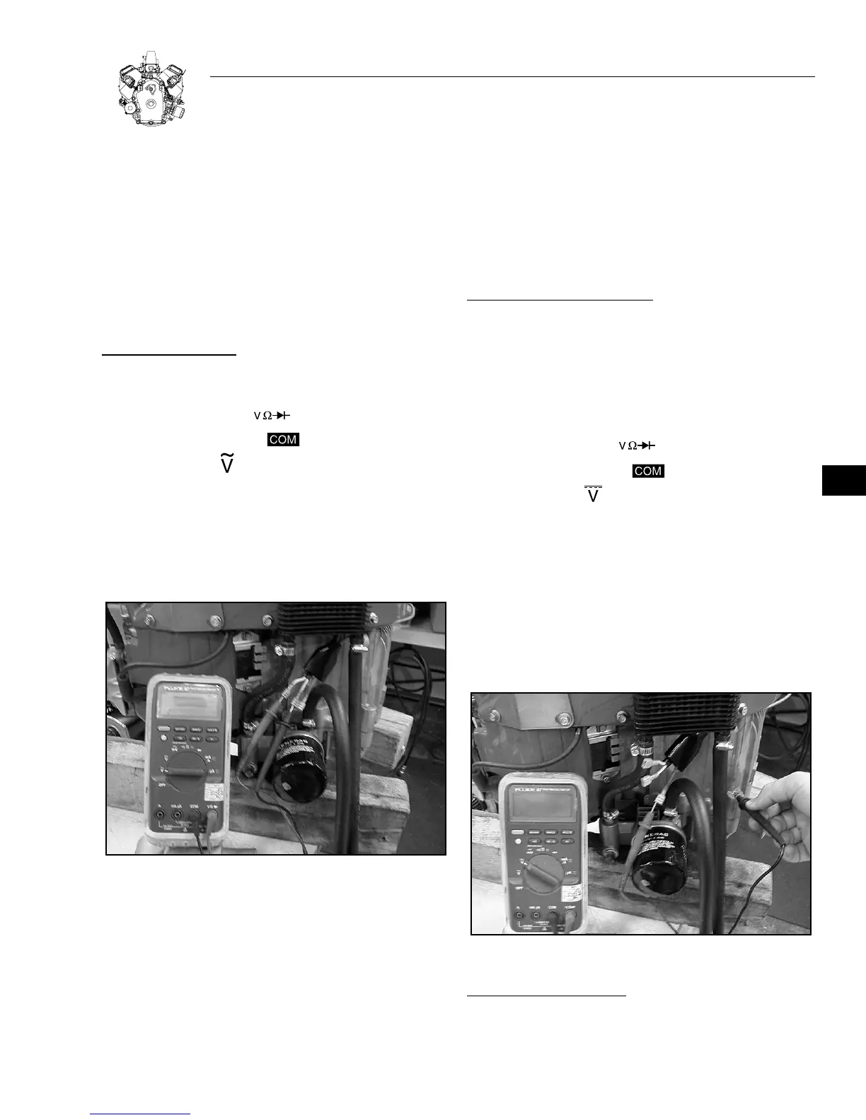
ALTERNATOR OUTPUT TEST:
Temporarily, disconnect stator wire harness from regulator-
rectifier.
1. Insert RED test lead into receptacle in meter.
2. Insert BLACK test lead into receptacle in meter.
3. Rotate selector to (AC volts) position.
*
CAUTION: ATTACH METER TEST LEADS TO AC OUTPUT TERMI-
NALS (WHITE WIRES) BEFORE STARTING ENGINE. IF STATOR
IS GROUNDED (DEFECTIVE), AND METER TEST LEADS CON-
TACT CENTER DC OUTPUT PIN, ARCING MAY OCCUR WHICH
MAY DAMAGE WIRING.
Figure 7-1. Testing AC Output
4. Attach RED and BLACK test lead probes to AC output ter-
minals (white wires), as shown in Figure. 7-1. (Meter test
clip leads may be attached to either AC output terminal.)
5. With the engine running at 3600 RPM, output should be no less
than:
26 Volts AC
6. If no or low output is found, check for bare wires or any other
obvious defects. If "shorted" leads are not visible, replace the
stator.
TESTING DC OUTPUT CHARGING WIRE:
A simple test may be performed to test the DC output charging wire
circuit. If a problem exists in the wiring it can be corrected before
testing regulator-rectifier.
Leave stator wire harness disconnected from regulator-
rectifier.
Equipment keyswitch must be in OFF position.
1. Insert RED test lead into receptacle in meter.
2. Insert BLACK test lead into receptacle in meter.
3. Rotate selector to (DC volts) position.
4. Attach RED test lead probe to DC output wire terminal (Red Wire),
Figure 7-2.
5. Attach BLACK test lead probe to negative battery ter-
minal.
6. Turn equipment keyswitch to ON position. Meter should display
battery voltage.
7. If meter does not display battery voltage, check for blown fuse
or broken or shorted wires.
Figure 7-2. Testing DC Output Wire
TESTING REGULATOR-RECTIFIER:
1. Using a digital multimeter, test battery voltage (engine NOT
running).
SECTION 7:
ALTERNATORS
7-1
7
 Loading...