Installation
10 Automatic Transfer Switch Owner’s Manual
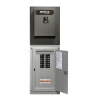
4. See Figure 3-2. Insert tab on each breaker (A) into
the hook on the bus (B). Push the breaker into the
bus until it snaps into place.
Figure 3-2. Install Breakers
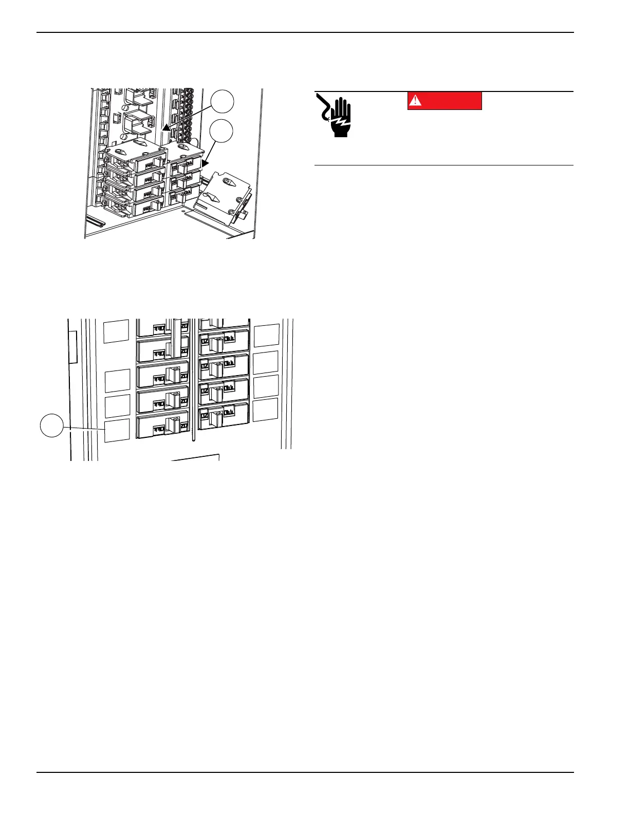
5. See Figure 3-3. Apply provided circuit directory
labels (C) and mark each circuit accordingly with a
pen.
Figure 3-3. Label Breakers
Installing Branch Circuit Conductors
1. Install properly sized branch circuit conductors into
the transfer switch through the knockouts provided.
Additional knockouts can be made in the field as
needed.
2. Connect the ungrounded branch circuit conductors
(hot conductors) to a properly sized circuit breaker
approved for use with the transfer switch.
3. Terminate the neutral conductor and equipment
grounding conductor of the branch circuit at the
neutral/equipment ground terminal bars.
4. Size all conductors, raceways, conduits, and
junction boxes, if required, to the applicable NEC
code articles and follow the NEC installation
requirements for the wiring method(s) selected.
NOTE: Multi-wire branch circuits must be installed in
accordance with NEC Article 210.4.
Connecting Power Source and
Generator Power Supply
Installation and interconnection diagrams are provided in
this manual.
NOTE: All installations must comply with national, state
and local codes. It is the responsibility of the installer to
perform an installation that will pass the final electrical
inspection.
• Connect utility supply at the utility service disconnect
circuit breaker terminals.
• Connect loads to the Integrated Load Center with
customer-supplied circuit breakers.
• See Figure 2-1. Connect generator to the generator
terminals (E1 and E2) on the transfer mechanism.
• Connect the generator neutral wire to the top neutral
lug or side lugs on the panelboard. An additional
neutral lug kit (pre-assembled on the 200A
panelboard) is provided for installation in the field if
needed.
• Connect neutral conductors to the lugs and terminals
along the neutral/ground bars in the panelboard
section of the transfer switch.
• Connect grounding electrode conductors to the
neutral terminal bars in the panelboard portion of the
switch.
000362
Electrocution. Turn utility and emergency
power supplies to OFF before connecting
power source and load lines. Failure to do so
will result in death or serious injury.
(000116)
DANGER
 Loading...


