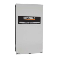
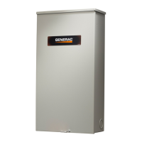
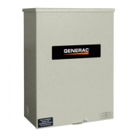
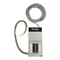
Automatic Transfer Switch Owner’s Manual iii
Section 1: Introduction and Safety
Introduction ......................................................... 1
Safety Rules ........................................................ 1
Safety Symbols and Meanings .......................... 1
Electrical Hazards ............................................... 2
General Hazards .................................................. 3
Section 2: General Information
Introduction ......................................................... 5
Unpacking ............................................................ 5
Equipment Description ....................................... 5
Transfer Switch Mechanism ....................................... 5
Load Center Circuit Breakers ..................................... 6
Service Disconnect Breaker and Terminal Ratings .... 6
Transfer Switch Data Decal ................................ 6
Transfer Switch Enclosure ................................. 6
Safe Use of Transfer Switch .............................. 6
Load Management Options ................................ 6
Smart A/C Module (SACM) ......................................... 7
Smart Management Module (SMM)
(Sold Separately) ............................................... 7
Application Considerations ......................................... 7
Section 3: Installation
Introduction to Installation ................................. 9
Mounting .............................................................. 9
Install Breakers ................................................... 9
Installing Branch Circuit Conductors ............. 10
Connecting Power Source and Generator Power
Supply .......................................................... 10
Connecting Start Circuit Wires ........................ 11
Connecting Smart A/C Module (SACM) .......... 11
Control of Air Conditioner Load ................................ 11
Auxiliary Contact .............................................. 12
Section 4: Operation
Functional Tests and Adjustments ..................13
Manual Operation ..............................................13
Close to Utility Source Side .......................................13
Close to Generator Source Side ................................14
Return to Utility Source Side .....................................14
Voltage Checks ..................................................14
Utility Voltage Checks ................................................14
Generator Voltage Checks ........................................14
Generator Tests Under Load ............................14
Checking Automatic Operation ........................15
Installation Summary ........................................15
Shutting Generator Down While Under Load ..15
Testing The Smart A/C Module ........................15
Testing The Smart Management Module .........16
Section 5: Drawings and Diagrams
Installation Drawings ........................................17
Installation Drawing No. 10000005900 (100A) ..........17
Installation Drawing No. 10000005900 (200A) ..........18
Interconnection Drawings ................................19
Interconnection Drawing 10000005901—
Air-Cooled 100A Generator (page 1 of 2) ........19
Interconnection Drawing 10000005901—
Air-Cooled 100A Generator (page 2 of 2) ........20
Interconnection Drawing 10000005901—
Air-Cooled 200A Generator (page 1 of 2) ........21
Interconnection Drawing 10000005901—
Air-Cooled 200A Generator (page 2 of 2) ........22
Interconnection Drawing 10000005855—
Liquid-Cooled 100A Generator (page 1 of 2) ...23
Interconnection Drawing 10000005855—
Liquid-Cooled 100A Generator (page 2 of 2) ...24
Interconnection Drawing 10000005855—
Liquid-Cooled 200A Generator (page 1 of 2) ...25
Interconnection Drawing 10000005855—
Liquid-Cooled 200A Generator (page 2 of 2) ...26
Table of Contents
 Loading...
