Installation
12 Automatic Transfer Switch Owner’s Manual
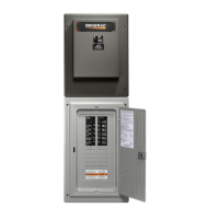
Figure 3-4. Typical SACM Connections
Auxiliary Contact
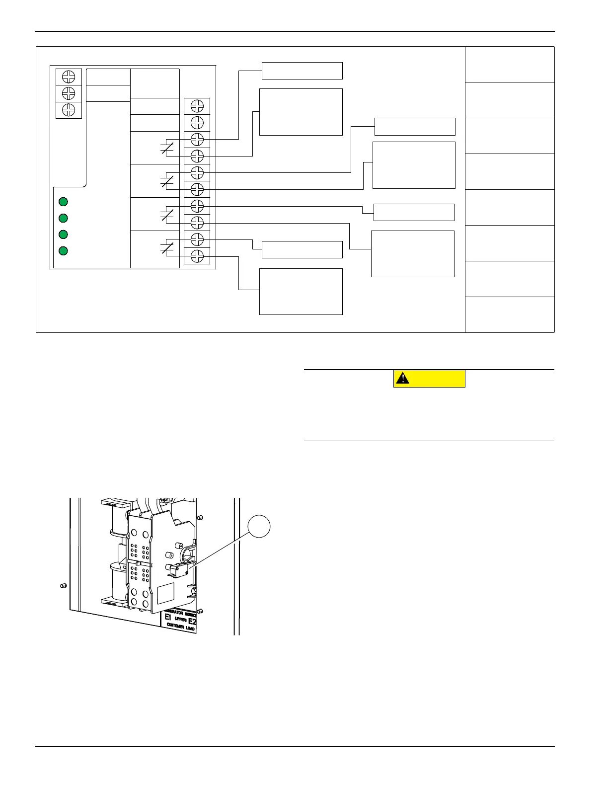
See
Figure 3-5
. If desired, there is one normally-closed
Auxiliary Contact (A) on the transfer switch to operate
customer accessories, remote advisory lights, or remote
annunciator devices. A suitable power source must be
connected to the common terminal. If needed, an extra
auxiliary contact can be added.
The auxiliary contact is normally closed when the transfer
switch is in utility mode. The contacts will open when the
transfer switch is in the standby power mode.
Figure 3-5. Auxiliary Contact
NOTE: Auxiliary Contact is rated 10 amps at 125 or 250
volts AC, and 0.6 amps at 125 volts DC.
A
Thermostat 1
B
Air Conditioner 1
C
Thermostat 4
D
Air Conditioner 4
E
Thermostat 2
F
Air Conditioner 2
G
Thermostat 3
H
Air Conditioner 3
0 GROUND
194 +12V
23 TRANSFER
A/C 1
A/C 2
A/C 3
A/C 4
A/C 1
A/C 2
A/C 3
A/C 4
T1
00 NEUTRAL
003693
A
B
C
D
E
F
G
H
003626
(000134a)
CAUTION
Equipment damage. Exceeding rated voltage
and current will damage the auxiliary contacts.
Verify that voltage and current are within specification
before energizing this equipment.
 Loading...


