Installation
Automatic Transfer Switch Owner’s Manual 9
Section 3: Installation
Introduction to Installation
This equipment has been wired and tested at the factory.
Installing the switch includes the following procedures:
• Mounting the enclosure.
• Connecting power source and load leads.
• Connecting the generator start and sensing circuit.
• Connecting any auxiliary contact (if needed).
• Testing functions.
Mounting
Mounting dimensions for the transfer switch enclosure
are in this manual. Enclosures are typically wall-
mounted. See Drawings and Diagrams.
This transfer switch is mounted in a ETL type 3R
enclosure. It can be mounted outside or inside and should
be based on the layout of installation, convenience and
proximity to the utility supply and load center.
Install the transfer switch as close as possible to the
electrical loads that are to be connected to it. Mount the
switch vertically to a rigid supporting structure. To prevent
switch distortion, level all mounting points. If necessary,
use washers behind mounting holes to level the unit.
Open Enclosure
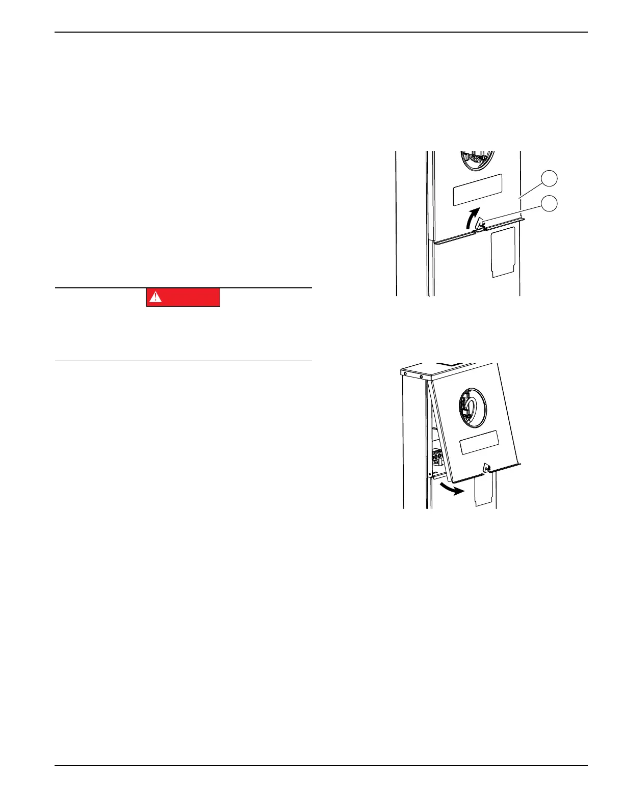
See Figure 3-1. First, remove outer top cover (A):
1. Rotate latch (B) clockwise until clear of latch hole.
Figure 3-1. Rotate Latch
2. See Figure 3-2. Tilt cover as shown and pull away
from enclosure.
Figure 3-2. Tilt Cover
See Figure 3-3. Remove outer bottom cover (C):
3. Remove thumb screw (D).
4. Slide slot (E) over retention tab.
5. Lower cover until clear of flange (F), and pull away
from enclosure.
Remove inner panel (G):
6. Loosen nut (H) until it clears t-slot (I) in inner panel.
7. Grasp inner panel at two cutouts (J—left and right).
Tilt inner panel as shown, passing nut through t-
slot.
8. Lower inner panel until clear of two retention slots
(K—left and right sides), and pull away from
enclosure.
(000119)
DANGER
Equipment malfunction. Installing a dirty or damaged
transfer switch will cause equipment malfunction and
will result in death or serious injury.

 Loading...


