4 Operator’s Manual for Portable Generator
Section 2 General Information and Setup
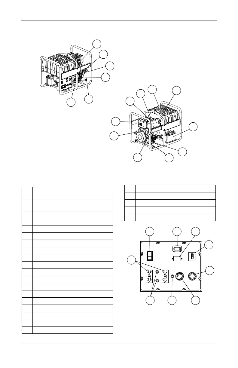
Figure 2-1. Features and Controls
TABLE 1. Generator Components
Figure 2-2. Control Panel
000711
15
13
7
19
10
14
21
22
9
8
12
14
6
20
17
24
1 120 Volt AC, 20 Amp, GFCI Duplex
Receptacle
2 120/240 Volt AC, 30 Amp Locking
Receptacle
3 120 Volt AC, 30 Amp Locking Receptacle
4 20 Amp Circuit Breakers
5 30 Amp Circuit Breaker
6Oil Drain
7 Air Filter
8 Decompression Lever
9 Fuel Tank
10 Grounding Lug
11 Start/Run Switch
12 Muffler
13 Fuel Cap/Fuel Gauge
14 Oil Fill (2 locations)
15 Recoil Starter
16 Main 23 Amp Breaker Switch
17 Fuel Return Hose
18 Hour Meter
19 Battery (if equipped)
20 Fuel Filter
21 Engine On/Off Lever
22 Fuel On/Off
23 Voltage Selector Switch
24 Fuel Primer Bulb

 Loading...


