XT8000E Series Portable Generator 5
2.1 — UNPACKING
• Remove all packaging material.
• Remove separate items.
• Remove the generator from carton.
2.1.1 — Documents and Accessories
(not shown)
Check all contents. If any parts are missing or damaged,
call 1-888-77LOWES.
• Product Registration Card
• Warranty and Emission Sheets
• 1 - Owner’s Manual
• 1 - Quart Oil - SAE 30W
• 1 - 20 ft. Extension Cord
• 1 - Battery Charger
• 1 - Oil Funnel
2.1.2 — Loose Components
• 1 - Hardware Bag (containing the following):
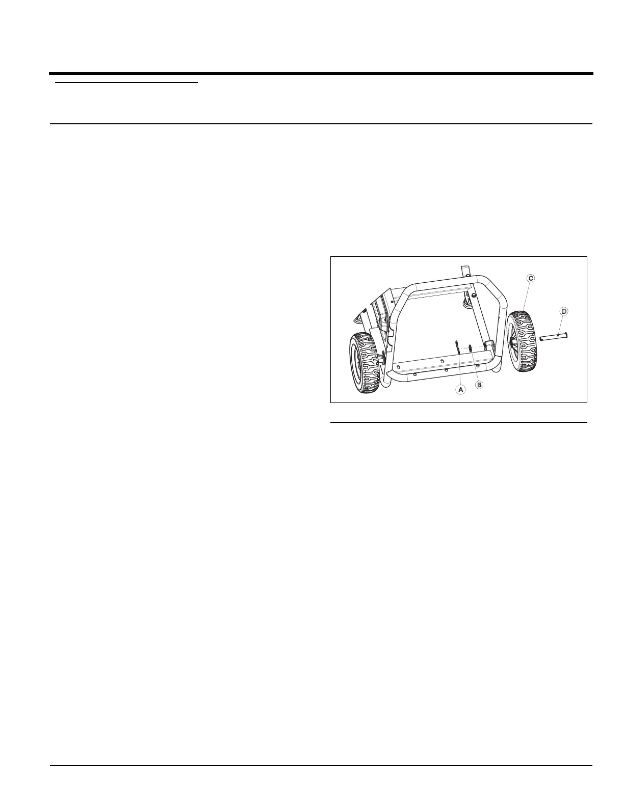
— 2 - Cotter Pins
(A)
— 2 - Washers (B)
— 2 - Never-Flat Wheels (C)
— 2 - Axle Pins (D)
— 2 - Frame Foot Assembly (E)
— 4 - Hex Flanged Nuts (M8) (F)
— 4 - Hex Bolts (M8) (G)
— 1 - Gasket (H)
— 1 - Control Guard (J)
— 4 - Allen Screw (4 mm) (K)
— 1 - Handle Assembly (L) (not in hardware bag)
— 2 - Hex Bolt (M8 X 55 mm) (M)
— 4 - Washer, Nylon (N)
— 2 - Nut, Hex Lock (P)
— 1 - Allen Hex Wrench (4 mm) (not shown)
2.2 — ASSEMBLY
The generator requires some assembly prior to usage. If
problems arise when assembling the generator, call 1-
888-77LOWES.
2.2.1 — Required Tools
— 1 - Ratchet wrench
— 1 - 13 mm socket
— 2 - 8 mm wrenches
— 1 - 13 mm wrench
— 1 - Needle nosed pliers
2.2.2 — Installing Wheels
NOTE:
The wheels are not intended for over-the-road use.
1. Install the Wheels as follows (Figure 2-1):
— Slide the Axle Pin through the Wheel, Wheel
Bracket on the frame and a 5/8" Flat Washer.
— Insert the Cotter Pin through the Axle Pin. Use the
needle nosed pliers to bend open to lock in place.
Figure 2-1. Wheel Assembly
2.2.3 — Installing Frame Feet and Control
Guard
2. Install the Frame Foot Assemblies as shown (Figure
2-2).
— Slide the M8 Hex Bolts through the holes in the
Frame Rail.
— Slide the Frame Foot onto the Hex Head Bolts.
Then install the Locking Flange Nuts. Tighten
securely using a ratchet, 13 mm socket and
13 mm wrench.
3. Install the Gasket and Control Guard (Figure 2-2).
— Place the Gasket and Control Guard in place
against the side panel opening. While holding the
Gasket and Control Guard, install the four retain-
ing screws. Thread all screws loosely before final
tightening any of them. Final tighten securely with
the 4 mm Allen wrench (provided).
Section 2 General Information

 Loading...