210 ONE MAN HOLE DIGGER, FORM GOM-1061-1189, VERSION 2.0, AUTHORIZATION: DVR, PAGE: 14
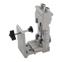
6) Move the throttle control lever to the one half
opened position. FIGURE 6.
FIGURE 6
7) Using the left hand, pull the recoil starter handle until
engine compression is felt. Use short, steady pulls until
the engine starts.
8) If the engine does not start after 3 to 5 pulls, pull the
choke control lever up and proceed to start the engine.
9) Allow the engine to properly "warm up" and operate
without the requirement for engine choke. As the
engine warms up, move the choke lever up to the full
open position. In cold weather, initial starting will
require more pulls because an extremely rich fuel/air
mixture is required. Check for proper centrifugal clutch
operation, excessive transmission noise and/or
vibration.
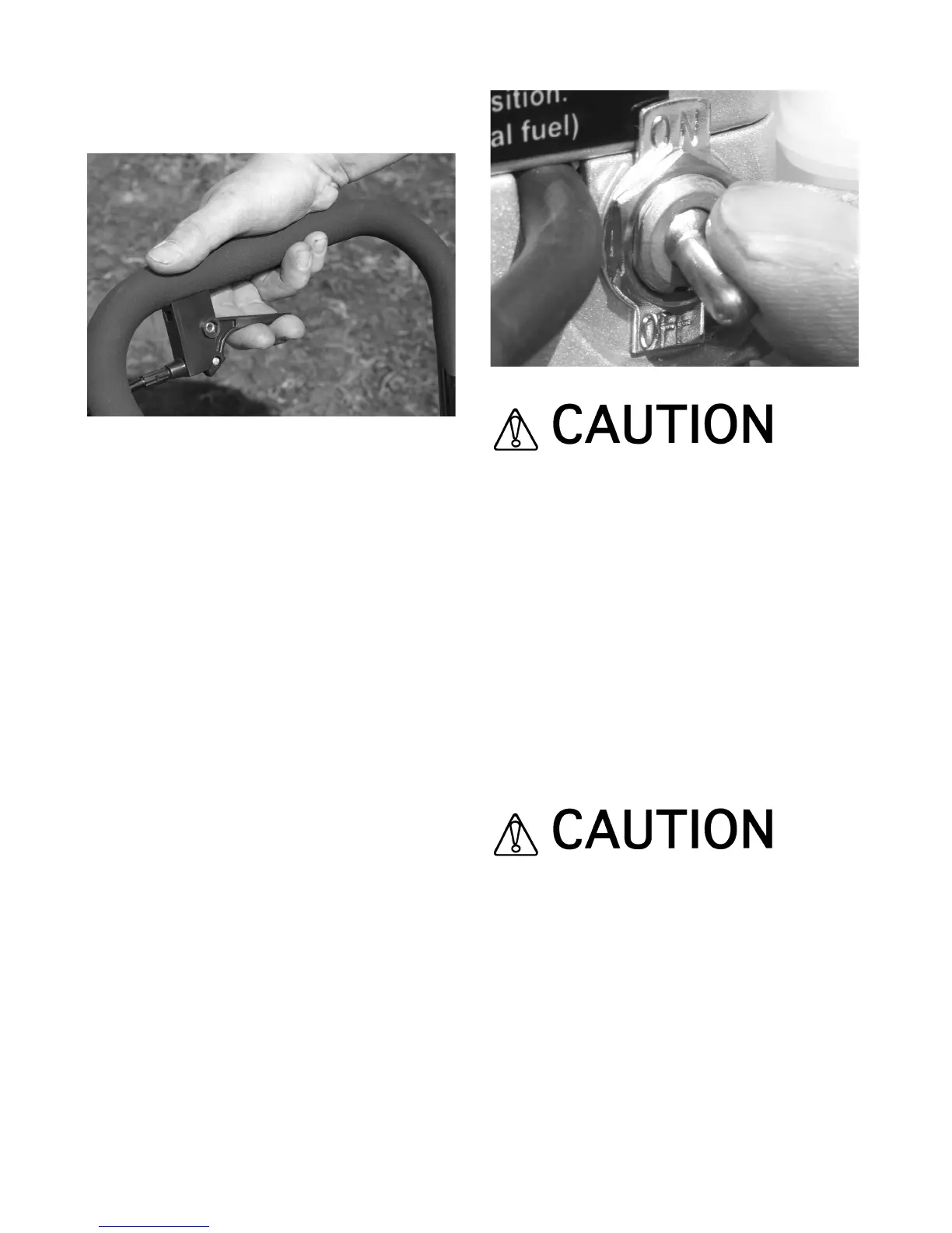
10) Stopping the Hole Digger is accomplished by
releasing the throttle control lever to its maximum,
closed (engine idle speed) position and then turning
the ignition ON/OFF switch to the OFF position.
FIGURE 7.
FIGURE 7
If the Hole Digger and/or an individual
component/accessory does not appear to be
functioning properly, STOP and do not further
operate the Hole Digger until the corrective action
has been completed. If there are any questions
regarding the proper operation of the Hole Digger,
contact the dealer or the Customer Service
Department for assistance BEFORE further
utilzation. There is no charge for this service.
OPERATING THE HOLE DIGGER.
1) Digging with the engine operating at full, governed
speed will allow the centrifugal clutch to become more
firmly engaged. This procedure will transmit more
usable power to the auger, resulting in greater
productivity and less component wear.
When digging in areas filled with known buried
obstructions such as tree roots, rocks and other
debris, operate the Hole Digger at less than full,
governed (an intermediate) speed to insure a more
rapid release of the centrifugal clutch when an
obstruction is encountered. This is an industry
wide operating procedure.
2) The Hole Digger is equipped with a centrifugal clutch
assembly within the transmission, designed to slip
whenever overloaded or if the auger comes in contact
with a buried obstruction. The term slippage is not
intended to infer that the centrifugal clutch assembly
 Loading...