SC24
UK
SC24
UK
12
13
FUNCTION PROGRAMMING (DIP SWITCH-SW1)
The settings are stored during the rest phase (gate closed).
DIP Status Functuion Description
DIP 1
DIP 2
OFF
OFF
STEP-BY-STEP WITH STOP
I Start pulse : OPEN
II Start pulse : STOP (will not reclose automatically)
III Start pulse : CLOSE
IV Start pulse : OPEN
DIP 1
DIP 2
ON
OFF
STEP-BY-STEP
I Start pulse : OPEN
II Start pulse : CLOSE
III Start pulse : OPEN
DIP 1
DIP 2
OFF
ON
CONDOMINIUM
During opening does not receive other Start commands after the first one; during Pause
subsequent Start commands reload the pause time
I Start pulse : OPEN
Subsequent Start pulses : Uninfluential
Pause from opening limit switch
Start pulse during pause : Reloads the pause time (if dip 6 ON)
or CLOSES (if dip 6 OFF)
Subsequent Start pulse : OPEN
DIP 1
DIP 2
ON
ON
DEAD MAN
If Start button is held down : OPEN
If Pedestrian button is held down : CLOSE
DIP 3 ON Enables pre-flashing of 2 seconds before motor activation during opening an d closing
DIP3 OFF
PRE-FLASHING
Disables pre-flashing
DIP 4 ON
Enables the safety device TEST before activating the opening and closing cycle.
The test consists of temporarily cutting the power to the devices (terminal 18 +SAFETY)
and checking proper switching of the contact (terminal 13 SAFETY).
The cycle can only start if the devices work perfectly, if not, three prolonged flashes
indicate the fault.
DIP 4 OFF
SAFETY DEVICE TEST
Disables the safety device test.
DIP 5 ON
When the photocell is intercepted during both opening and closing, the gate motion is
locked until the photocell is freed. Subsequently, there is always an opening phase.
DIP 5 OFF
PHOTOCELL DURING OPENING
Disables the photocell function during opening.
DIP 6 ON
Enables automatic closing after the pause time adjustable with the trimmer TR5 PAUSE
between 2 and 215 seconds.
DIP 6 OFF
AUTOMATIC CLOSING
Disables automatic closing.
DIP 7 ON
Enables deceleration during both opening and closing when the respective limit switch is
intercepted. The deceleration speed is adjusted with the trimmer TR3 SLOW. This function
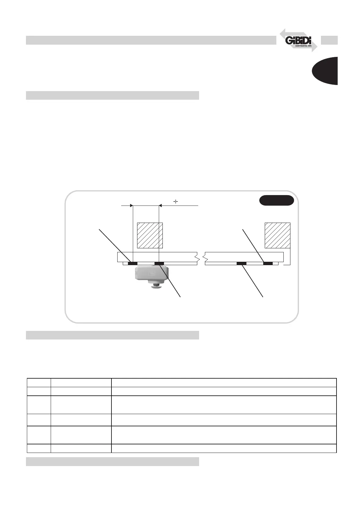
provides for use of 4 magnets (see drawing 2)
DIP 7 OFF
DECELERATION
Disables the deceleration function. Only 2 magnets are required (see drawing 2)
DIP 8 ON Reduces the pause time to 3 seconds after intervention of one of the photocells.
DIP 8 OFF
FAST CLOSING
Disables the fast closing function.
DIP 9 ON Not used
DIP 9 OFF Not used
DIP 10 ON
Supplies the LEDs (which will come on depending on the respective contact).
After proper installation, the LED power supply can be deactivated to save energy.
DIP 10 OFF
LED POWER SUPPLY
Disables the warning LED power supply.
! DIP 1 and DIP 2 both OFF: Step-by-step with stop
! DIP 3 OFF: Pre-flashing disabled
! DIP 4 OFF: Safety device test disabled
! DIP 5 OFF: Opening photocell disabled
! DIP 6 ON: Automatic closing enabled
! DIP 7 OFF: Deceleration disabled
! DIP 8 OFF: Fast closing disabled
! DIP 9 OFF: Uninfluential
! DIP 10 ON: LEDs powered
DEFAULT SETTINGS
TRIMMER ADJUSTMENT
! The trimmers TR1, TR2, TR3, TR4 can be adjusted also during gate movement and hence the effect
immediately be checked.
! The trimmer TR5 is stored only during the rest phase (gate closed).
! TRIMMER TR1 TR3 TR5 adjusted to minimum
! TRIMMER TR2 TR4 adjusted to maximum
Fig.2Fig.2
DEFAULT SETTINGS
Closing limit switch
motor stop
Limit switch slowing
down in closing
Limit switch slowing
down in opening
Opening limit switch
motor stop
400 500mm
Trimmer Function Description
TR1 FORCE Adjusts the motor FORCE level. The force is increased by turning the trimmer clockwise.
TR2 AMP.FORCE
Adjusts the intervention threshold of the anti-crushing function during non-decelerated motion. When it intervenes the
motion is locked and inverted for 2 seconds in order to free the obstacle. The intervention threshold is increased by
turning the trimmer clockwise.
TR3 SLOW
Adjusts the DECELERATION level. Deceleration is decreased by turning the trimmer clockwise (turning clockwise the
gate speed/force is increased)
TR4 AMP. SLOW
Adjusts the intervention threshold of the anti-crushing function during slow motion. When it intervenes the motion is
locked and inverted for 2 seconds in order to free the obstacle. The intervention threshold is increased by turning the
trimmer clockwise.
TR5 PAUSE Adjusts the PAUSE TIME from 2 to 215 seconds. The value is increased by turning the trimmer clockwise.
 Loading...