- 55 - Motherboard Components
Chapter 4 Motherboard Components
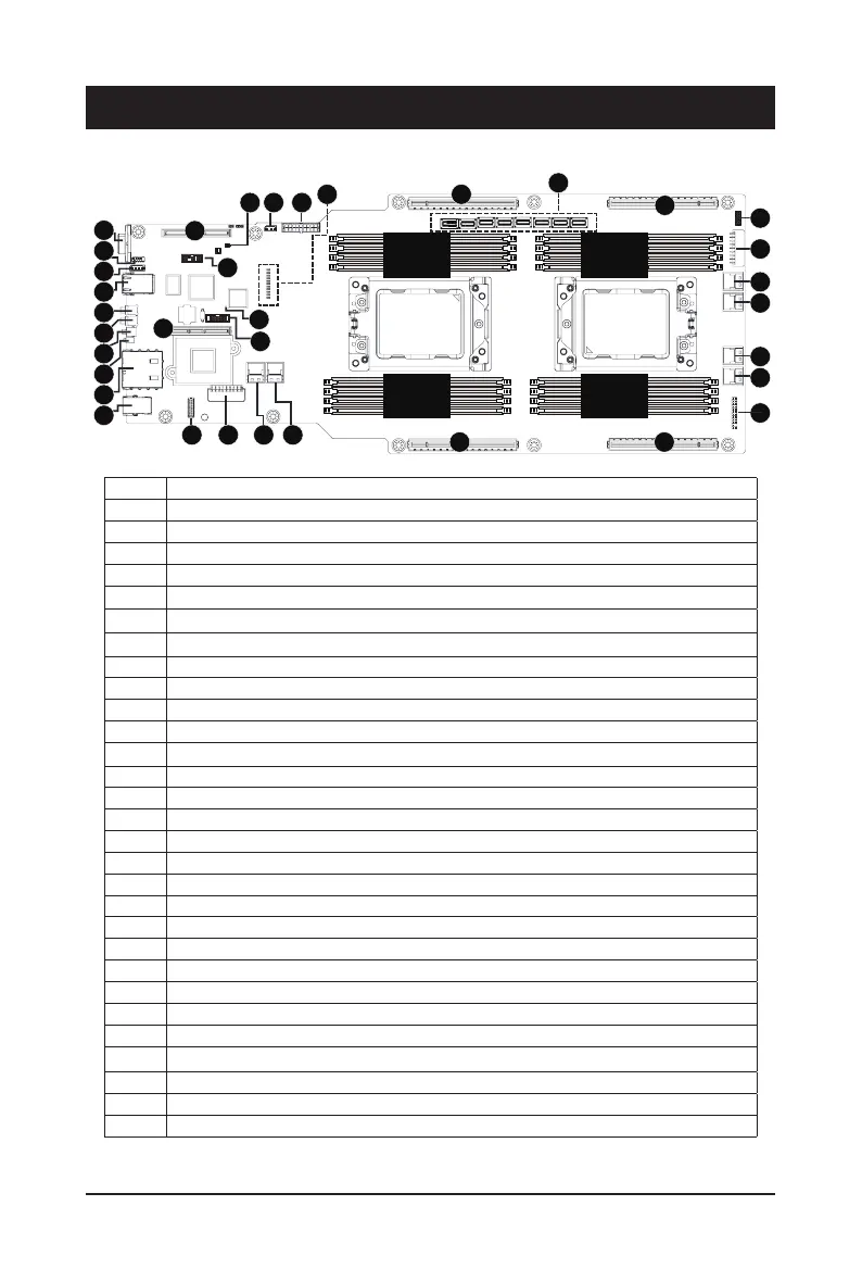
4-1 Motherboard Components
Item Description
1 Rear VGA Port
2 Serial Port Connector
3 IPMB Connector
4 10/100/1000 Server Management LAN Port
5 Power Button with LED
6 ID Button with LED
7 Reset Button (top)/ NMI Button (bottom)
8 System Status LED
9 10G RJ45 Type LAN Port #1/#2
10 USB 3.0 Port x 2
11 HDD Back Plane Board Connector
12 2 x 9 Pin Power Connector (for CPU0)
13 SlimLine 4i Connector #0 (SL_SATA0)
14 SlimLine 4i Connector #1 (SL_SATA1)
15 PCIe x16 Slot #2
16 PCIe x16 Slot #4
17 Front Panel Header (primary)
18 SlimLine 4i Connector #3 (U2_P1_P0_1/support NVMe)
19 SlimLine 4i Connector #3 (U2_P1_P0_0/support NVMe)
20 SlimLine 4i Connector #4 (SL_SATA4)
21 SlimLine 4i Connector #3 (SL_SATA3)
22 2 x 9 Pin CPU Power Connector (for CPU1)
23 Front Panel Header (secondary/for power distribution board)
24 PCIe x16 Slot #3
25 SlimLine 4i Connector x 8 (U2_P1_G1_7~4, U2_P0_G3_3~0/Right to Left)
26 PCIe x16 Slot #1
27 Related System Voltage Status LED
28 2 x 9 Pin System Power Connector
29 12V Standby Power Connector (for system power)
CPU0 CPU1
DIMM_P0_D0
DIMM_P0_C0
DIMM_P0_B0
DIMM_P0_A0
DIMM_P0_E0
DIMM_P0_F0
DIMM_P0_G0
DIMM_P0_H0
DIMM_P1_P0
DIMM_P1_O0
DIMM_P1_N0
DIMM_P1_M0
DIMM_P1_I0
DIMM_P1_J0
DIMM_P1_K0
DIMM_P1_L0
1
2
3
4
5
6
7
8
9
10
11 12 13 14
15 16
17
18
19
20
21
22
23
24
2627
25
282930
32
31
31
33
34
 Loading...