EasyManuals Logo

Gigabyte GA-Z170X-Gaming G1 User Manual

Gigabyte GA-Z170X-Gaming G1
136 pages
To Next Page IconTo Next Page
To Previous Page IconTo Previous Page
Page #27 background imageLoading...
Page #27 background image
- 27 -
Hardware Installation
1-11 Installing the GC-USB3.1 BAY
Step 1:
Install the GC-USB3.1 BAY in the chassis and fasten it with screws.
Then connect one end of the cable to the SATA Express connector
on the motherboard.
Step 3:
Connect the SATA power cables from the power supply to the SATA
power connectors on the GC-USB3.1 BAY. You must connect the two
connectors with separate power cables.
Step 2:
Connect the other end of the cable to the SATA Express connector
on the GC-USB3.1 BAY.
Please connect the cable to the SATA Express connector
consisting of the SATA3 0, 1 or SATA3 2, 3 connectors.
The Power Delivery function can be enabled only when the
system is powered on.

Table of Contents

Questions and Answers:

Question and Answer IconNeed help?

Do you have a question about the Gigabyte GA-Z170X-Gaming G1 and is the answer not in the manual?
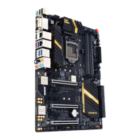
Gigabyte GA-Z170X-Gaming G1 Specifications

General IconGeneral
Form FactorE-ATX
ChipsetIntel Z170
CPU SocketLGA 1151
Memory TypeDDR4
Memory Slots4
Maximum Memory64 GB
PCI Express x16 Slots4
PCI Express x1 Slots3
AudioCreative Sound Core3D
Audio Channels7.1
RAID SupportRAID 0, 1, 5, 10
PS/2 Port1
HDMI1
DisplayPort1
Memory SpeedDDR4 2133/2400/2666/2800/3000/3200/3300/3333/3400/3466/3600/3733/3866 MHz
SATA 6Gb/s Ports6
M.2 Slots3
USB 3.1 Ports1 Type-A, 1 Type-C
USB 3.0 Ports8
USB 2.0 Ports6
LAN2 x Killer E2400 Gigabit LAN
DVI-D1
Multi-GPU Support4-Way SLI/CrossFire Support

Related product manuals