3. Installation 3. Installation
.17..16.
3.4 Electrical Connections
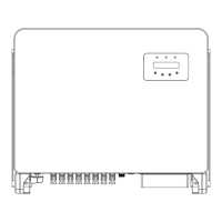
3) Align the mounting plate with the holes, Insert the combination bolt (M10X40)through the
mounting plate into the hole. Secure the bracket to the metal frame firmly with the supplied
fastener. Torque the nut to 30Nm-35Nm (22.13 ft.lbs-25.82 ft.lbs).
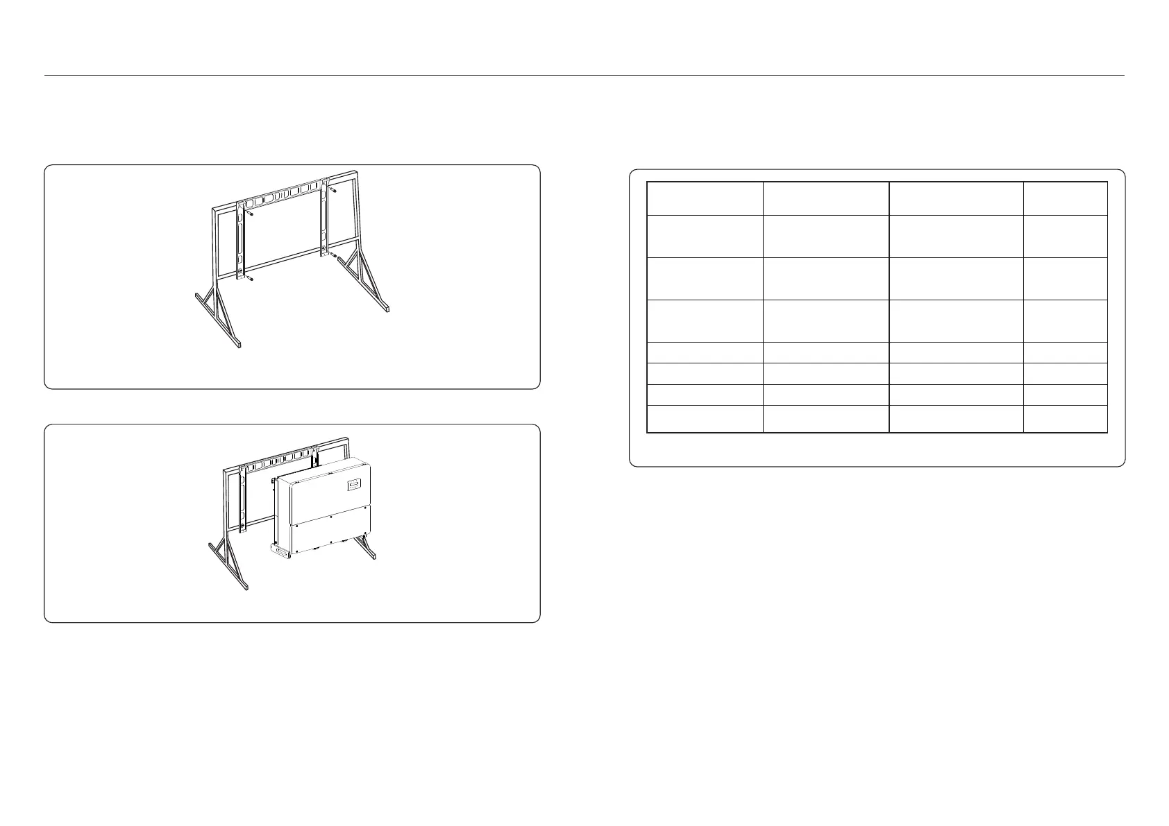
4) Lift the inverter above the bracket and then slide down to make sure they match perfectly.
Figure 3.13 Construction bolt
Figure 3.14 Mount the inverter
The electrical connection of the inverter must follow the steps listed below:
1. Switch the Grid Supply Main Switch (AC) OFF.
2. Switch the DC Isolator OFF.
3. Connect the AC wires.
4. Connect the DC wires.
Table 3.1 Electrical connection
Parts
Connection Cable size
Torque
DC terminal
Ground terminal
Grid terminal
RS-485 terminal
RJ45 terminal
COM terminal
PV String
AC Ground
AC Grid
Communication cable
Communication cable
Wi-Fi/Cellular stick
Network cable
NA
NA
NA
DC surge protection
device
NA NANA
24-14AWG
7.4-14.7 ft.lbs
7.4-14.7 ft.lbs
7.4-14.7 ft.lbs
1.2-1.5 ft.lbs
2AWG - 350MCM
(Recommend 4/0 AWG)
2AWG - 350MCM
(Recommend 4/0 AWG)
2AWG - 350MCM
Minimum 1/2 AC
The inverter is designed with a wiring box at the bottom. Before the electrical connection, it
requires the cover for the bottom wiring box to be removed. Table 3.1 describes the information
about the components in the wiring box. All wiring must meet the local or national standards.
 Loading...