This function is for maintenance personnel only, wrong operation
will prevent the inverter from reaching maximum power.
2. Volt-Watt (Not Required)
Description: Inverter will change the active output power based on voltage change.
Note: This Setting is NOT required by UL1741SA Standards.
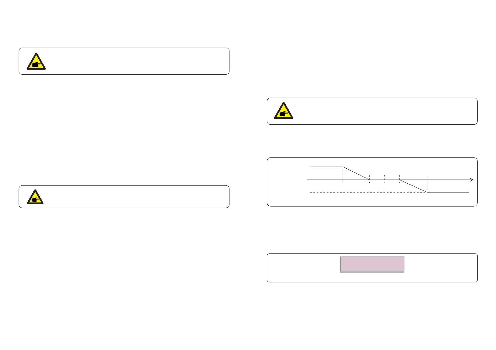
3. Volt-Var (Default)
Description: Inverter will change the reactive output power based on voltage change.
Q1,cap
Q2=Q3= 0
Q4,ind
V1 V2 Vnom V3 V4
Figure 6.21 Volt- VAR curve for Q(V)
Default Settings for UL1741SA:
Q1: (0-60%) Default +30% Q4: (-60%-0%) Default -30%
Rated 600V Grid
V1:(277-346V) Default 303V V2: (277-346V) Default 340V
V3:(346-415V) Default 349V V4: (346-415V) Default 381V
Figure 6.22 Volt-VAR
Voltage1: 303V
Voltage2: 340V
1.NULL
Description: Inverter is not under any working mode.
6. Normal operation6. Normal operation
6.7.8 STD Mode Settings
1. Working Mode Set
2.Power Rate Limit
3.Freq Derate Set
4.10mins Voltage Set
5.Power Priority
6.Initial Settings
7.Voltage PCC Set
Selecting “STD Mode. Settings” displays the sub-menu shown below:
This section is applicable to maintenance personnel only.
Solis US version inverters have Seven working modes:
1. NULL
2. Volt-watt
3. Volt-Var
4. Fixed-PF
5. Reac-power
6. Power-PF
7. VgWatt-UL
Based on UL1741SA, working mode 1,3,4,7 can be used by grid operator.
6.7.8.1 Working Mode Set
6.7.8.1.1 With UL Standard selected
There are TWO situations with different grid standards selected.
NOTE
The following modes are for "UL-600V".
.49..48.
 Loading...