3.4.4 Connecting power supply
Before connecting check power supply rating as well as power supply unit voltage rating.
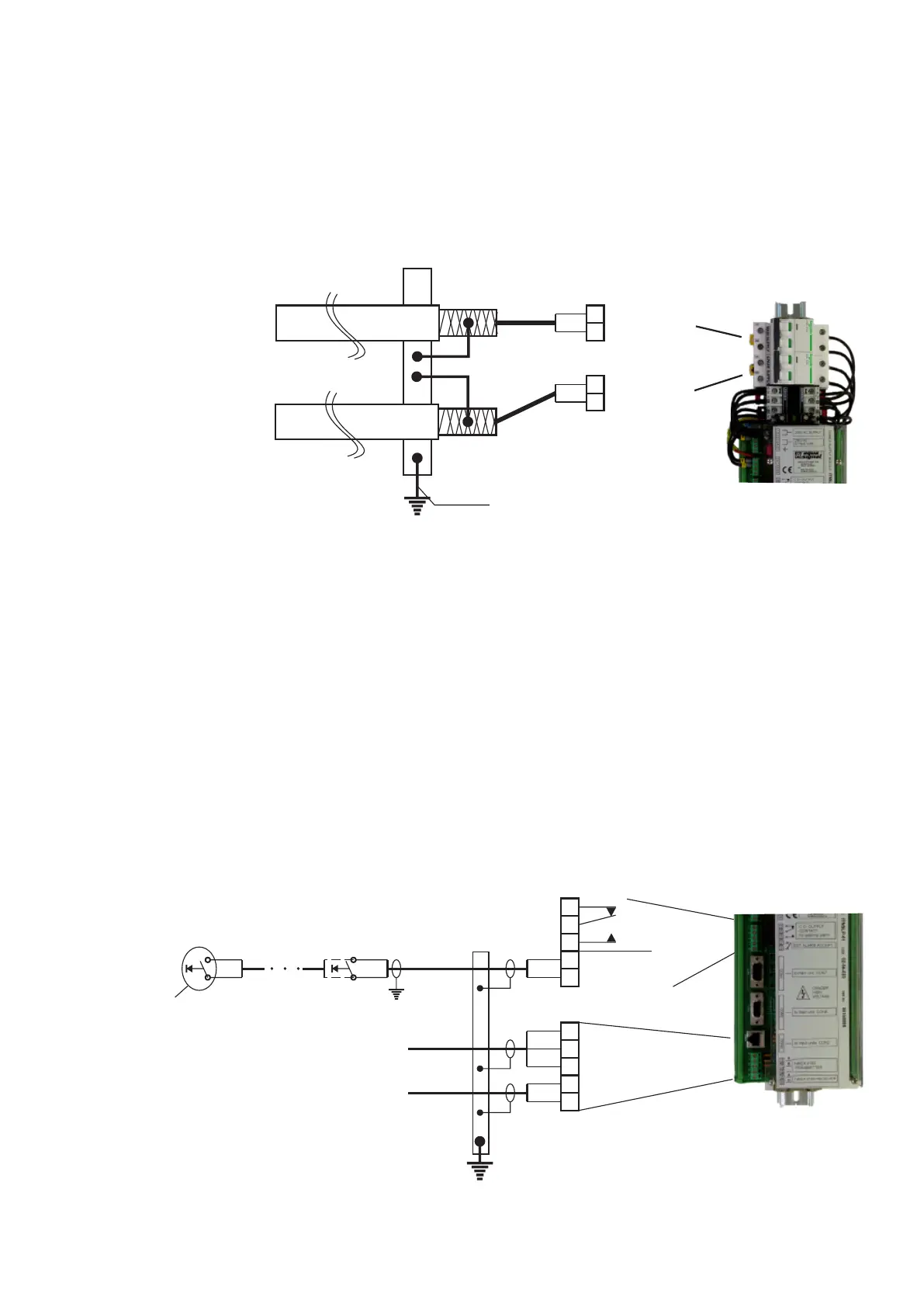
Power suppy for navigation and signal lights controller are to be connected according prepared connection
drawings. Power supply wires / ables need to be in accordance with systems’ power consumption. Connect
cable sheild to equipotential bonding circuit.
At this point do not turn on power supply!!!
16mm2
1
3
1
2
MAIN
POWER
SUPPLY
1
3
1
2
SPARE
POWER
SUPPLY
3.4.5 Connecting input/output contacts and NMEAcommunication
For connection to other systems following input/output contacts are provided:
1. Alarm output - voltage-free change over contacts, max. 250V AC/1A acctivated in case of broke light
circuit and power/system failure.
2. External alarm accept input - normally open voltage-free contact, when acctivated quits main unit
buzzer only (sound alarm).
For communication with other systems NMEA 0183 communication is provided. ITNSL-01 NMEA 0183
TRANSMITTER and RECEIVER are used as bi-directional interface to transfer external alarm from
Navigation and signal lights controller type ITNSL-01 to external systems and audio alarm acknowledgement
from external systems.
Connect as shown bellow. Connect shield of cables to instrument earth.
1112
13
EXTERNAL ALARM
OUTPUT CONTACT
14
15
EXTERNAL ALARM
ACCEPT INPUT
Push button for
external alarm accept
16
17
181920
PE
NMEA 0183 RECEIVER**
($IIACK sentence)
Tx-A
Tx-B
-
NMEA 0183
TRANSMITTER**
($IIALR sentence)
Rx-A
Rx-B
IE
Power supply module
ITNSLP-01
Power supply module
ITNSLP-01
16
 Loading...