27
221469B
11.6 Gas Rate Modulation - Honeywell
The minimum gas rate is factory preset and no adjustment
should be required.
ALWAYS CHECK HOT WATER BURNER PRESSURE FIRST
- REFER TO SECTION 11.5.
To check the minimum gas rate, first make sure that the boiler
is isolated from the electrical supply at the external isolator.
Disconnect one of the electrical connectors (grey), from the
modulator, see diagram 11.3.
Insulate the connector to make sure that it does not contact any
metallic part of the boiler.
Switch on the electrical supply.
Fully open a hot water draw off tap and the main burner will light
at the minimum gas rate.
Check that the burner pressure is 2.1mbar +/-0.2mbar, (0.9in
wg +/-0.1in wg). If this is incorrect, it may be adjusted by
removing the cap and turning the larger adjusting nut of the
modulator, (anti-clockwise to decrease the pressure).
If the above adjustment was necessary, it will be essential to
check that the maximum pressure can still be obtained. Push
the spindle gently in to the stop and hold it in. The maximum
pressure should not be less than 16mbar, (6.4in wg). If this
pressure cannot be achieved, obtain it by turning the small
adjusting nut, (clockwise to increase the pressure). Always
adjust the minimum pressure first.
If the maximum pressure is unattainable, check that the gas
supply is of adequate size, refer to Section 1.7 “Gas Supply”.
Put right as necessary.
Isolate the boiler from the electrical supply then reconnect the
modulator cable and refit the cap.
11.6 Gas Rate Modulation - SIT
The minimum gas rate is factory preset and no adjustment and
should be required.
Always check hot water burner pressure first - refer to Section
11.5.
To check the minimum gas rate, first make sure that the boiler
is isolated from the electrical supply at the external isolator.
Disconnect one of the electrical connectors, grey, from the
modulator, see diagram 11.3.
Insulate the connector to make sure it does not contact any
metallic parts.
Switch on the electrical supply.
Fully open a hot water draw off tap and the main burner will light
at the minimum gas rate.
Check that the burner pressure is 2.1mbar +/- 0.2mbar (0.9in
wg +/-0.1in wg). If this is incorrect, it may be adjusted by turning
the centre white adjuster screw of the modulator, anti-clockwise
to decrease, whilst at the same time stopping the larger brass
nut from turning, see diagram 11.3.
Isolate the boiler from the electrical supply then reconnect the
modulator cable and refit the cap.
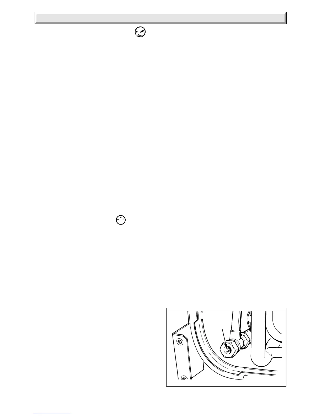
11.7 Domestic Water Flow Rate
Adjust the water throttle to obtain a flow rate of 9.5Litre/min
(2.1gall/min), (clockwise to increase), see diagram 11.5. This
is equal to 7 seconds to fill a 1Litre container (4seconds to fill a
1pint container). Close the tap when adjustment is satisfactory.
The minimum water flow rate is 3.6Litre/min (0.8gal/min)
11 Commissioning
equivalent to 16.5 seconds to fill a 1Litre container (9.5 seconds
to fill a 1pint container). If this flow rate cannot be achieved,
check that there is no partial blockage and that the supply is of
adequate size. Put right as necessary.
Close the hot water draw off tap.
11.8 Burner Pressure - Heating
The burner pressure is factory preset and no adjustment should
be required.
Check that all remote heating system controls, room thermostats,
integral clock and the like are switched on/programmed and
calling for heat.
Set switch “C” to “On” as shown in diagram 11.1.
The pump will circulate water through the boiler and the main
burner will light.
Check that the burner pressure, with the heating system cold to
prevent any modulation of the gas pressure, is within +/-
0.2mbar (+/-0.08in wg) of 8.0mbar (3.3in wg), the central
heating pressure.
If the burner pressure is incorrect, it may be adjusted to the
correct setting by turning the central heating gas pressure
adjuster (potentiometer), using an insulated screwdriver, see
diagram 10.1. Turn the adjuster slowly, always making
adjustment by reducing below the required pressure then
increasing up to the required setting, (turn clockwise to increase).
Isolate the boiler from the electrical supply.
Remove the pressure gauge and tighten the test
point screw.
Note. It will be necessary when finally mounting the clock to
reposition the gas valve solenoid and thermocouple lead.
Fit the cover and secure the control housing with the screws
previously removed.
Test for gas soundness around the burner pressure test point
with the main burner alight, using leak detection fluid. Take care
not to splash any of electrical components.
SIT only - Refit the piezo bracket.
11.9 Temperature Settings
The domestic hot water outlet and central heating flow
temperatures are factory preset and sealed, therefore cannot
be adjusted.
The nominal temperature setting for the domestic hot water
outlet is 60
o
C (140
o
F) at a flow rate of 3.6Litre/min (0.8gall/min).
The nominal maximum flow temperature setting for central
heating is 82
o
C (180
o
F).
2801
Diagram 11.5
DOMESTIC
HOT
WATER
THROTTLE
 Loading...