28
221469B
11 Commissioning
6623
SECURING
NUT
CATCH
ASSEMBLY
SPACER
PLASTIC
BUSH (2
)
HINGE
PIN
HINGE PIN
HINGE PIN RETAINING
BRACKET
BRACKET
SECURING
SCREW
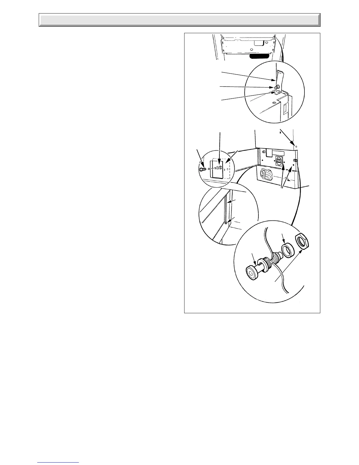
Diagram 11.6
PLASTIC COVERS
COVER
PLATE
NUT &
WASHER(2)
OUTER CASE
SECURING
SCREWS (4)
SCREW (2)
11.10 Heating System - Commissioning
Check that all remote controls and integral clock are calling for
heat.
Fully open all radiator valves, flow control valve “A” and bypass
valve “B”, see diagram 4.2.
Set the heating system in operation and balance the radiators.
Adjust the control valve “A” to achieve the required system
differential temperature between the flow and return.
Turn off all radiators, then adjust bypass valve “B” to achieve the
same temperature difference between the boiler flow and
return.
Refer to Section 4.6 and diagram 4.1 and 4.1A.
Allow the system to reach maximum temperature then switch
off, isolate the boiler from the electrical supply and drain the
system rapidly whilst still hot.
Fill and vent the system as described in Section 11.2 “Filling the
Central Heating Circuit”. Add inhibitor, if applicable, refer to
Section 4.10 “Inhibitor”.
Lower the pressure to the initial cold fill design pressure, using
the external draining tap, close to the boiler, refer Table 2 and
Section 4.11.
Lock or remove the handles from the spindles of flow control
valve “A” and bypass valve “B” to prevent unauthorised
adjustment.
The permanent mains electrical supply to the boiler must not be
switched off whilst the pilot flame is alight.
11.11 Completion
The user control door is designed for left or right hand hinging.
If required the hinge can be moved to the other side to that
supplied, as follows:
Remove the hinge pin bracket securing screw then remove the
hinge pin retaining bracket and holding the door, remove the
hinge pin. Prise out the hinge pin bushes and fit on to the
opposite side of the door, see diagram 11.6.
Remove the screw and nut and fit to the opposite side of the
case. After removing the hinge pin retaining bracket refit the
door and hinge pin. Refit the hinge pin retaining bracket and fit
the securing screw.
Fit the catch assembly, supplied in the loose items pack, see
diagram 11.6.
If required, fit the plastic covers to hide the bracket securing
screws.
Change the position of the “Push” label to suit the new door
opening.
Clock/timer, if fitted, remove the screws, nuts and washers to
release the cover plate, see diagram 11.6.
Stick the casing label to the right hand side of the clock/timer.
Fit the outer case, secure with the four screws, see
diagram 11.6.
Note: Secure with the two outer screws only if there is no clock/
timer fitted.
Set the boiler and any remote heating control to the desired
settings, then close the door.
11.12 Instruct the User
Instruct and demonstrate the lighting procedure, then advise
the user of the efficient and safe operation of the boiler.
Instruct and demonstrate the operation of any heating system
controls.
Advise the user on the use and maintenance of any scale
reducer and pass on any relevant instructional documents.
Advise the user that to ensure the continued efficient and safe
operation of the appliance it is recommended that it is checked
and serviced at regular intervals. The frequency of servicing will
depend upon the particular installation and usage, but in general
once a year should be enough.
Draw attention, if applicable, to the current issue of the Gas
Safety (Installation and Use) Regulations, Section 35, which
imposes a duty of care on all persons who let out any property
containing a gas appliance.
It is the Law that any servicing is carried out by a competent
person.
Advise the user of the precautions necessary to prevent damage
to the system and building in the event of the heating system
being out of use during frost and freezing conditions.
Advise the user that the permanent mains electrical supply
must not be switched off whilst the pilot is alight.
Reminder - Leave these instructions with the user.
 Loading...