CHECKING BELT TENSION
Checking Belt Tension on the Surface Drive does not require removal of the rear access
panels. An inspection hole on the side of the frame is provided to inspect and check belt
tension from outside of the frame.
Belt tension should be checked every 30-50 hours of run time as described below and
readjusted if necessary.
1. Locate the black hole plug on the side of the frame behind the engine.
2. Carefully slip a knife blade behind the plug flange and pry it out of the hole.
3. Use a flashlight to look inside the hole and locate the belt. When using the tension
tester, force must be applied to the belt by pushing the tester in the center of the
belt width. The inspection hole may or may not be centered on the belt width.
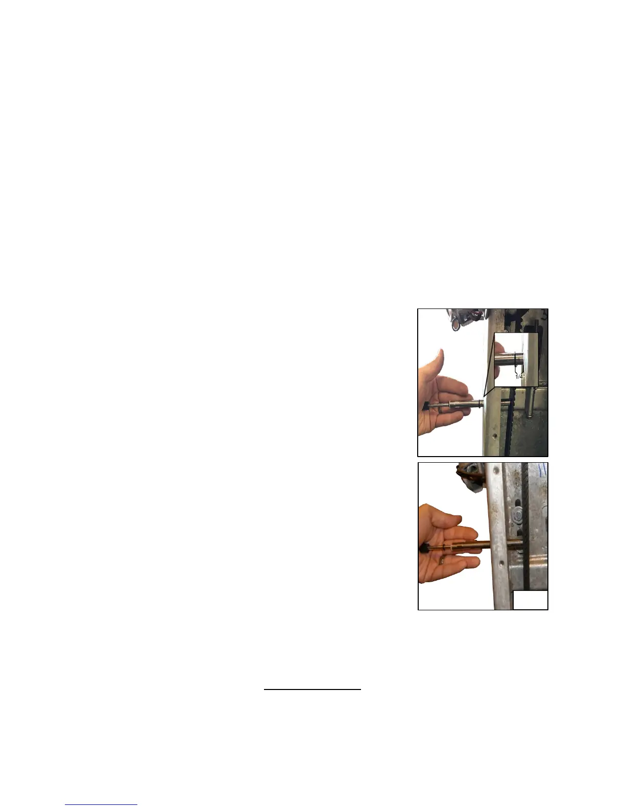
4. Insert tension gauge (Gates # 7401-0076) through the
hole in drive housing and set large O-ring ¼” from the
frame. Be sure to use the inch scale and not the
metric scale on the tester. (Fig. 1)
5. Slide small O-ring against the large part of the gauge.
Make sure the tension gauge is in the middle of the belt.
Push the gauge in until the large O-ring touches the
housing. Remove the tester from the hole and view the
small sliding “O” ring location on the force scale. The
force applied to deflect the belt is indicated by the
location of the bottom of the “O” ring on the force scale.
(Fig. 2)
6. Repeat steps 4-5 at least three times or until you
achieve the same result for each measurement.
7. The desired tension is 13-21 pounds with a target of
17 pounds with 1/4” deflection on an existing belt
using Gates belt gauge # 7401-0076. If the belt
tension is less than 13 pounds it will be necessary
to adjust belt. Tension a new belt to 21 lbs. to allow
for stretching. A new belt will stretch over night without running the engine.
If the measured force falls below specs shown below, re-tension the belt as
described on the following page (15).
All FNR Models
Force = 13-21 lbs.
Deflection = 1/4”
 Loading...