gpelectric.com | [page 23]
INSTALLATION
3.3.1 DC WIRING SIZING
The distance between the battery bank and the GP-ISW should be as short as possible to
achieve maximum eciency and to reduce re hazards. The size of the cable should be thick
enough to limit the voltage drop to less than 2% when carrying the maximum input current to
prevent frequent low-input voltage warnings and shutdown. Only use high quality copper wire.
For greater eciency, the cables should be as short as possible. The combined cable length
should be no more than 10ft (3m). Keeping your wire runs as short as possible helps to prevent:
low voltage shutdowns and nuisance tripping of the DC breaker because of increased current
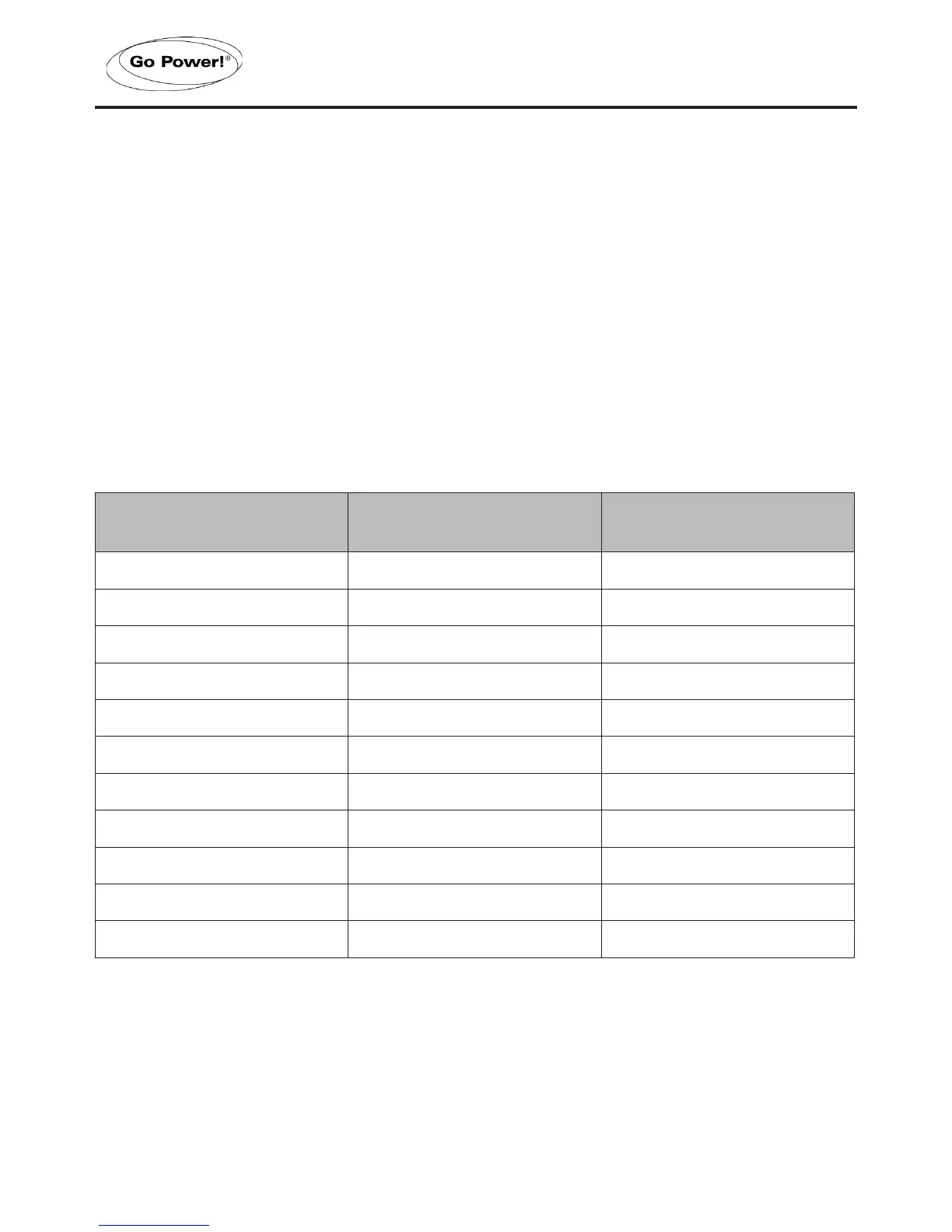
draw. The table below shows the recommended DC cable size, fuses/circuit breakers and
DC grounding cable sizes for the GP-ISW (Note: these values are correct for cables in free
air, not conduit)
Model Wire AWG Inline Fuse / Circuit Breaker
GP-ISW700-12 #6 F-110A
GP-ISW700-24 #10 F-110A
GP-ISW1000-12 #4 F-110A
GP-ISW1000-24 #8 F-110A
GP-ISW1500-12 #2 F-200A
GP-ISW1500-24 #6 F-200A
GP-ISW2000-12 #2/0 F-300A
GP-ISW2000-24 #4 F-200A
GP-ISW3000-12 #4/0 F-400A
GP-ISW3000-24 #2 F-300A
GP-ISW4000-24 #2/0 F-400A
 Loading...