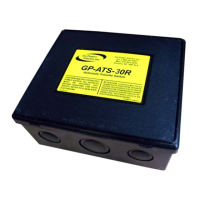
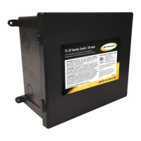
Go Power! TS-30
Owner’s Manual
3
1. Introduction
The Go Power! Electric Transfer Switch-30 amp (TS-30) provides automatic power
switching between two separate 120 volt AC input sources, including power cords,
onboard generators, or onboard inverters. The TS-30 will sense the presence of
available supplies and automatically select the proper one.
The TS-30 can be installed at the electrical entry of the RV on the line side of the
main distribution panel, or it can be installed on the load side of the panel between
the main panel and a sub panel, allowing switching for either the entire electrical
load or only designated circuits.
2. INSTALLATION
READ AND FOLLOW ALL SAFETY INSTRUCTIONS
2.1 DISCONNECT POWER
Make sure the generator is off, the external power cord is unplugged, and the
inverter, if any, is shut off.
2.2 MOUNTING LOCATION
The TS-30 mounting location may be on any interior surface where the unit will be
out of direct weather. The chosen location must be accessible after installation is
complete to facilitate future servicing. If possible, mount the TS-30 near the power
cord entry or the location of the generator output. Typical locations include under
counter cabinets, below closet compartments, inside the bed pedestal or cabinets,
overhead cabinets, under-floor storage compartments accessed from the vehicle
exterior, etc.
2.3 ELECTRICAL PREPARATION
Any numbered knockout on the TS-30 can be used for installation. Choose a
knockout that will facilitate installation and service within the selected mounting
area.
2.4 MOUNTING
Mount the TS-30 with screws through holes provided in bottom corners of the can.
The unit should be screwed to a solid surface firmly enough to hold its weight during
vehicle operation.
2.5 ELECTRICAL CONNECTIONS
1. Attach an 8-gauge chassis ground wire to the transfer switch ground bar. A
direct access hole to the ground bar is provided through the enclosure for
convenience.
2. Determine proper connections of wire conductors to electrical terminals. On 120
VAC wiring the ground wire is bare or green, the neutral wire is white, and the
hot wire is black.
3. Strip the outer jacket from all of the incoming cables and strip insulation from all
ends of the copper conductors. Insert cables through clamps in openings. Do
not tighten cable clamps at this time.
4. Route internal ground wires around lower area of enclosure and secure to
ground wires away from electrical contacts on components to avoid the
possibility of electrical short-circuit.
5. Connect the ground wires to the ground bar. Tighten terminals to a minimum of
20 inch-pounds.
CAUTION:
TO prevent exposure
to foreign
contaminants, do not
mount the transfer
switch in an engine
compartment under
kitchen sink drains
or water pipes within
the battery
compartment or any
compartment
designed for storage
of flammable liquids
such as gasoline.
 Loading...