Go Power! TS-30
Owner’s Manual
6
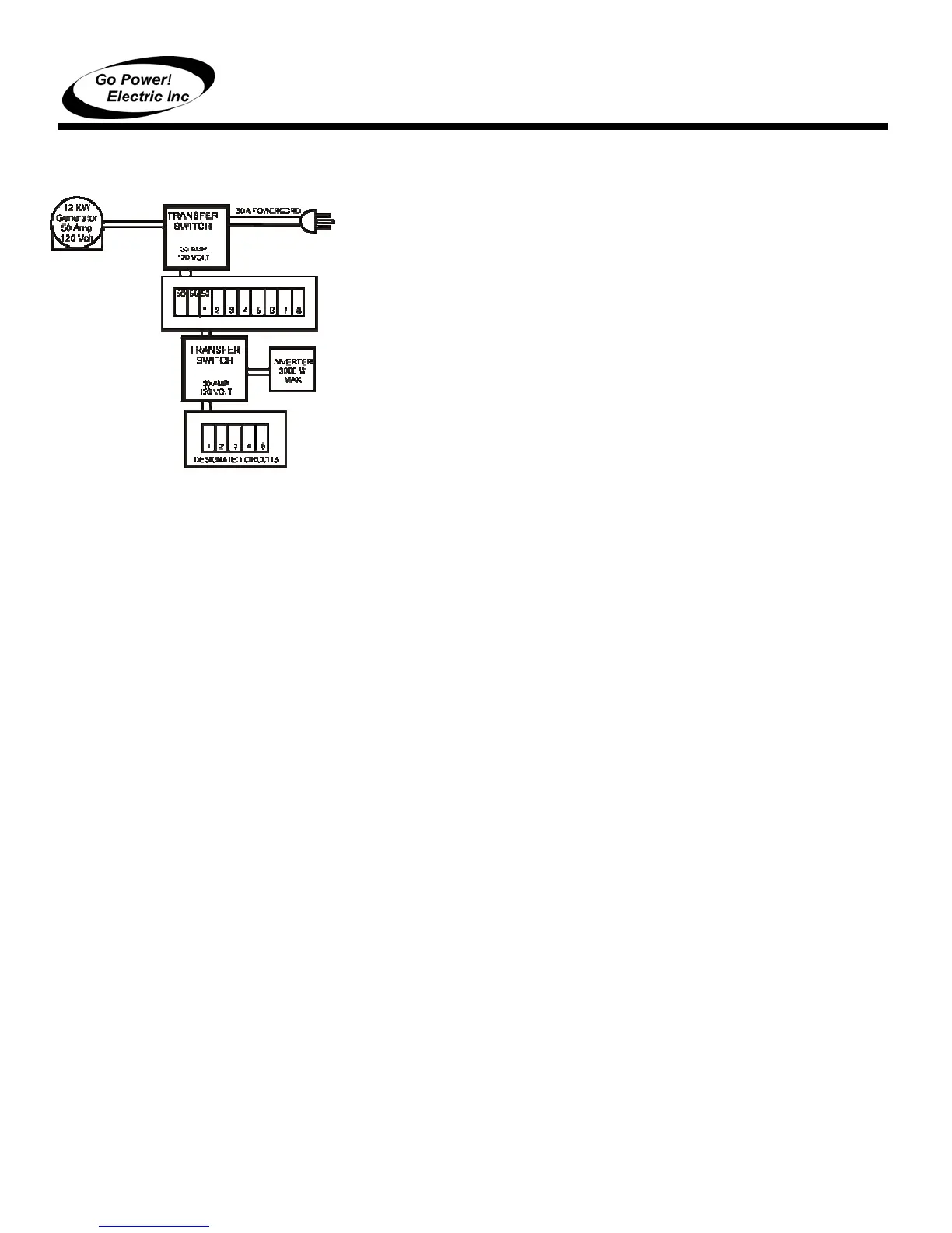
2.5.3 INSTALLATION IN HYBRID SYSTEM FOR DESIGNATED
CIRCUITS (CONFIGURATION D)
The TS-30 A can be installed between inverter (default) and a circuit
panel supplied by a larger amp alternating power supply (dominant).
1. Connect the inverter to terminals 7 and 8.
2. Connect the 30-amp branch circuit to 5 and 6.
3. Connect the designated circuit panel to the output terminals.
The inverter will only supply the load in the absence of the 50 amp
power supply, in which case, only the load designated to the 30 amp
branch circuit is supplied. The timer delay bypass switch on the TS-30
should be in the ON position.
3. OPERATIONAL TESTING
READ AND FOLLOW ALL SAFETY INSTRUCTIONS
1. Plug in the power cord. If the main panel circuit breakers are
switched on, RV load should operate normally. Unplug the power
cord.
2. Start the generator. There is a pre-programmed 20-30 second delay in the
transfer switch. The delay is designed to allow the generator a brief warm-up
period. When the delay completes its cycle the switch should engage and the
RV load should operate normally. An audible click should sound as the switch
engages.
3. Shut down the generator. As the generator winds down the switch should
disengage without chatter or cycling. An audible click should sound as the
switch disengages.
4. Plug in the power cord. Start the generator. After the preprogrammed delay, the
switch should transfer power automatically from the power cord to the
generator. Listen for the audible click as the switch transfers, as there will likely
be no other indication that the switch has engaged. Shut down the generator
and unplug the powercord.
5. On transfer switch arrangements with three power supplies, plug in the power
cord, start the generator, and turn on the inverter. With all three supplies
energized at the same time, the switch will select the generator for the primary
supply choice. Shut down the generator. The switch will transfer to the power
cord. Unplug the power cord. The switch will transfer to the inverter. The
inverter should always be connected so that it is only selected in the absence of
both the other supplies.
4. TROUBLESHOOTING
4.1 LOW VOLTAGE
Low voltage is harmful to most appliances. Contactor-based transfer switches are
also affected by low voltage; if the voltage level drops far enough the contactor
points will “chatter”. Sustained contact chattering can cause transfer switch damage.
Switches that have been damaged by chattering need to be returned to the factory
for replacement.
4.2 GENERAL LOW VOLTAGE
Low voltage can be caused by low voltage conditions such as an RV park with
inadequate wiring for crowded camper conditions where everyone’s electricity
suffers (brownout). In this case a voltmeter will be helpful and will show a low
voltage reading from the park receptacle, even before the RV is plugged in. When
D
50 Amp Hybrid
System
50 A 240 V Switch
Powercord
Generator
20 A 120 V Switch
Inverter
(Switching
designated circuits
to sub-
anel
 Loading...