Go Power! TS-30
Owner’s Manual
4
6. Connect the neutral (white) wire connections.
7. Connect the hot wire(s) (black).
8. To connect the wire leads, hold the wires parallel to each other so that the wire
tips are even, then secure with a wire nut. Use the proper size nut. Manually
tighten nuts as tightly as possible. Verify that all connections are tightened.
9. Tighten cable clamps on switch enclosure.
10. Attach lid. The lid is designed to snap on and should not open without deliberate
effort.
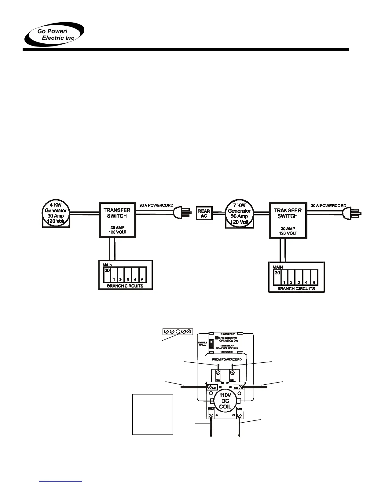
2.5.1 INSTALLATION BETWEEN POWERCORD AND GENERATOR
(CONFIGURATIONS A, B)
1. Connect the power cord leads to terminal 7 and 8 (on the narrow end of the
relay); these are the normally closed (N.C.) contacts.
2. Connect the generator leads to terminals 5 and 6 (on the shoulders of the
relay); these are the normally open (N.O.) contacts.
3. Connect output to panel to terminals 3 and 4 (on the wide end of the relay). The
TS-30 is designed with a time delay module to provide generators a brief warm-
up period before supplying the load. The bypass switch on the time delay
module should be in the “off” position (marked “1”). See Diagram 1.
Diagram 1 – Typical Generator Powercord Connection
To
panel
Hot
Hot
Neutral
Neutral
Ground
From
Generator
N
tr
l
From
Generat
r H
t
Switch Priority
Override Mode:
Generator
Default Mode:
Generator
30 Amp System
Powercord /
30 Amp System
Powercord /
7 KW Generator
Output split
between panel
and rear AC
B
 Loading...