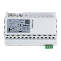
Access panel
ON
1 2 3 4 5 6
SW1
NA2
+
AP-
C1
NA1
AP+
C2
AP+ AP-
P1 P2
BUSBUS
_
AP1
NA2
+
AP-
C1
NA1
AP+
C2
AP+ AP-
P1 P2
BUSBUS
Relay 2Relay 1
_
12Vdc
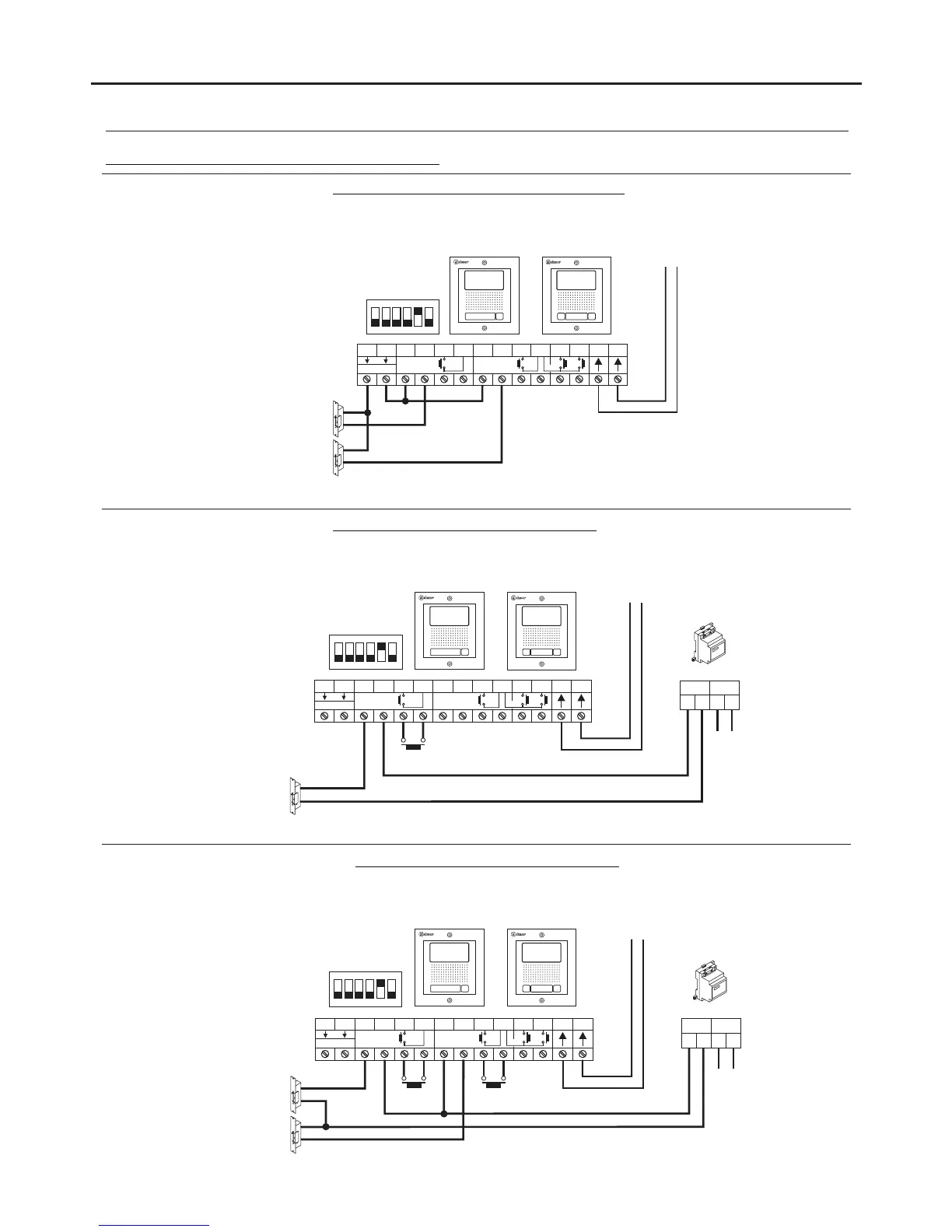
Connection of 2 DC lock releases without 'AP':
Important: With 2 DC lock releases, it is not possible to use the “AP” door release buttons.
(1)
Mains
230Vac
SEC
~~ ~~
PRI
TF-104
Lock release
max
. 12 Vac/850mA.
Connection of 1 AC lock release with 'AP':
NA2
+
AP-
C1
NA1
AP+
C2
AP+ AP-
P1 P2
BUSBUS
Relay 2Relay 1
_
12Vdc
(1)
To the FA-GB2/A
power supply
(1)
Lock release
max
. 12 Vdc/270mA.
Connection of 2 AC lock release with 'AP':
SEC
PRI
TF-104
Access panel
ON
1 2 3 4 5 6
SW1
Access panel
ON
1 2 3 4 5 6
SW1
WIRING DIAGRAMS:
18
Relay 2Relay 1
12Vdc
Lock release
max
. 12 Vac/850mA.
~~ ~~
AP1 AP2
Mains
230Vac
Connection of Golmar DC and AC lock releases.
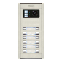
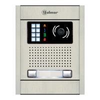
STAINLESS STEEL NEXA MODULAR GB2 VIDEO DOOR ENTRY SYSTEM KIT – HOUSES
or
or
To the FA-GB2/A
power supply
or
To the FA-GB2/A
power supply
Important: Fit the varistor supplied with the kit directly to the terminals of the lock release.
Important: Fit the varistor supplied with the kit directly to the terminals of each of the 2 lock releases.
*
*
*
*
*
 Loading...