Figure 6.2-2
Block Diagram of & GW10K-DT refer to Figure 6.2-2:GW09K-DT & GW12K-DT
DC
Switch
PV1+
PV1-
PV2+
PV2-
L1
L2
L3
N
PE
DC
SPD
DC
EMI
Filter
AC
EMI
Filter
LC
Filter
3-level
Inverter
Circuit
MPPT2
Circuit
MPPT1
Circuit
DC
SPD
DC
EMI
Filter
AC Isolation Relay
Figure 6.2-1
Block Diagram of and GW4000L-DT~GW6000L-DT 6.2-1:GW4000-DT~GW6000-DT refer to Figure
DC
Switch
PV1+
PV1-
PV2+
PV2-
L1
L2
L3
N
PE
DC
EMI
Filter
AC
EMI
Filter
LC
Filter
3-level
Inverter
Circuit
MPPT1
Circuit
MPPT1
Circuit
DC
EMI
Filter
AC Isolation Relay
6.2 Block Diagram
23 24
7 Maintenance
Regular maintenance ensures a long operating life and optimal efficiency of the entire PV plant.
Caution: Before maintains please disconnect the switch on AC and DC sides. Wait 10 seconds until the residual voltage has been
drained.
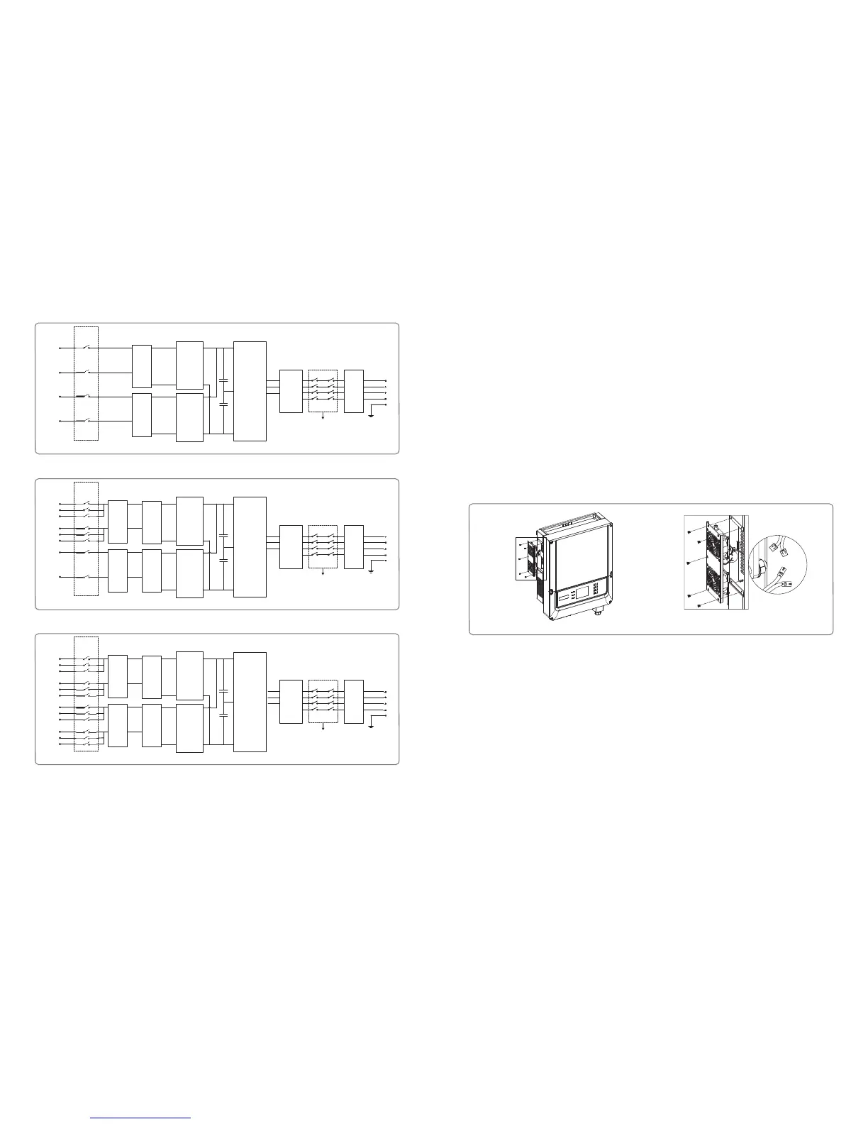
7.1 Cleaning the Fans
DT series inverter is fitted with two fans on its left side. The fan intakes and handle covers should be cleaned yearly with a vacuum
cleaner. For more thorough cleaning, completely remove the fans.
●Disconnect the switch on AC and DC sides.
●Wait 10 seconds until the residual voltage has been drained and the fans are no longer turning.
●Disassembly the fans (refer to Figure 7.1-1).
1)Loosen the five M4 screws with a crosshead screwdriver, then remove the fans out the cabinet about 50mm slowly.
2)Open the lockers of the two fan connectors and remove them from housing, then take the fans away.
●Clean the ventilation grid and the fan with a soft brush, a paint brush, a cloth, or compressed air.
●Reassembly the out fans into cabinet.
Figure 7.1-1
Figure 6.2-3
DC
Switch
PV1+
PV1-
PV2+
PV2-
L1
L2
L3
N
PE
DC
SPD
DC
SPD
DC
EMI
Filter
DC
EMI
Filter
AC
EMI
Filter
LC
Filter
3-level
Inverter
Circuit
MPPT2
Circuit
MPPT1
Circuit
Block Diagram of GW15K-DT & GW17K-DT & GW20K-DT & GW25K-DT refer to Figure 6.2-3:
AC Isolation Relay
 Loading...