12
Normal
2012-03-26
Vp1=200.3V
Ip1= 15.8A
Vp2=300.8V
Ip2= 12.5A
VL1=230.5V
VL2=232.5V
VL3=233.0V
IL1=15.5A
IL2=15.3A
IL3=15.4A
F1=50.00HZ
F2=50.01HZ
F3=50.00HZ
Model
GW17K-DT
Ver:1.00
Error Log
Date&Time
Language
Histogram
Error Log
Date&Time
Language
Histogram
Error Log
Date&Time
Language
Histogram
Error Log
Date&Time
Language
Histogram
Error Log
Date&Time
Language
Histogram
Set Zigbee
WiFi Reset
WiFi Reload
70% Rated
Set Zigbee
WiFi Reset
WiFi Reload
70% Rated
Set Zigbee
WiFi Reset
WiFi Reload
70% Rated
Set Zigbee
WiFi Reset
WiFi Reload
70% Rated
Set Modbus
Shadow OFF
Error Log
Date&Time
Language
Histogram
Over
Temperatur
13:29:25
2012-01-18
………
Utility
Loss
13:12:25
2012-03-25
Error Log
Date&Time
Language
Histogram
Set Time
13:12:25
2012-03-25
Set Zigbee
WiFi Reset
WiFi Reload
70% Rated
Set Zigbee
WiFi Reset
WiFi Reload
100% Rated
Language:
English
语言:
中文
Error Log
Date&Time
Language
Histogram
…………
WiFi
Reset
Set Zigbee
WiFi Reset
WiFi Reload
70% Rated
Enter
WiFi
Resetting
WiFi
Successful
Reset
WiFi
eset R Failed
Year Mode
Month Mode
Day Mode
Hour Mode
Error Log
Date&Time
Language
Histogram
Year Mode
Month Mode
Day Mode
Hour Mode
Year Mode
Month Mode
Day Mode
Hour Mode
Enter
Year Mode
2012
Month Mode
2012
Day Mode
2012-03
Year Mode
2012-03-26
Set Modbus
Shadow OFF
Set Zigbee
WiFi Reset
WiFi Reload
70% Rated
WiFi
Reload
Enter
WiFi
Reloading
Set Modbus
Shadow OFF
Set Usual
ADDR:247
Shadow OFF
Down
Set Usual
ADDR:247
Shadow OFF
ADDR: 247
Enter
Enter
Year Mode
Month Mode
Day Mode
Hour Mode
Down Or Up
Some times
ADDR:
100
Set Usual
ADDR:100
Shadow OFF
WiFi Model
Enter
ESC
Down
Enter
WiFi
eload
Success
R
WiFi
Reload
Failure
Set Modbus
Shadow OFF
Set Modbus
Shadow ON
Enter
Enter
Enter
Enter
*
*
Wait
Wait
Enter
Up
Down
Up
Up
Down
Up
Down
Down
Up
Up
Down
Up
Down
Up
Down Down
Up
Down
Up
Up
Down
ESC
ESC
Up
Down
Up
Down
Up
Down
ESC
ESC
Up
Down
Up
Down
ESC
ESC
Up
Down
ESC
Up
Down
Up
Down
Up
Down
Up
Down
Up
Down
Up
Down
ESC
ESC
*For SDT series , LCD display as “Set Local”, not “Set Zigbee”.
For SDT series, there is no “Set Modbus” and “Shadow OFF”.
11
4.2 User Interface and Controls
LED lights in Yellow/Green/Red correspondently refer to POWER/RUN/FAULT.
Yellow: Light on indicates the inverter is electrified.
To WiFi model inverters, If the Power light flashes every 0.5sec, it indicates the connection between inverter and your WiFi
router is abnormal; If the Power light flashes every 2.5sec, it indicates the inverter has successfully connected to your WiFi
router however connection with Web Server is abnormal; If the Power light keeps on continuously, it indicates WiFi
monitoring is all normal.
Green: If the RUN light keeps on, it indicates inverter operating normally. If the RUN light is flashing, it indicates the inverter is
undertaking self-checking.
Red: If the Fault light keeps on, it indicates inverter abnormal conditions and require service.
4 System Operation
4.1 LED Lights
POWER
RUN
FAULT
ESC
Up
Down
Enter
ESC
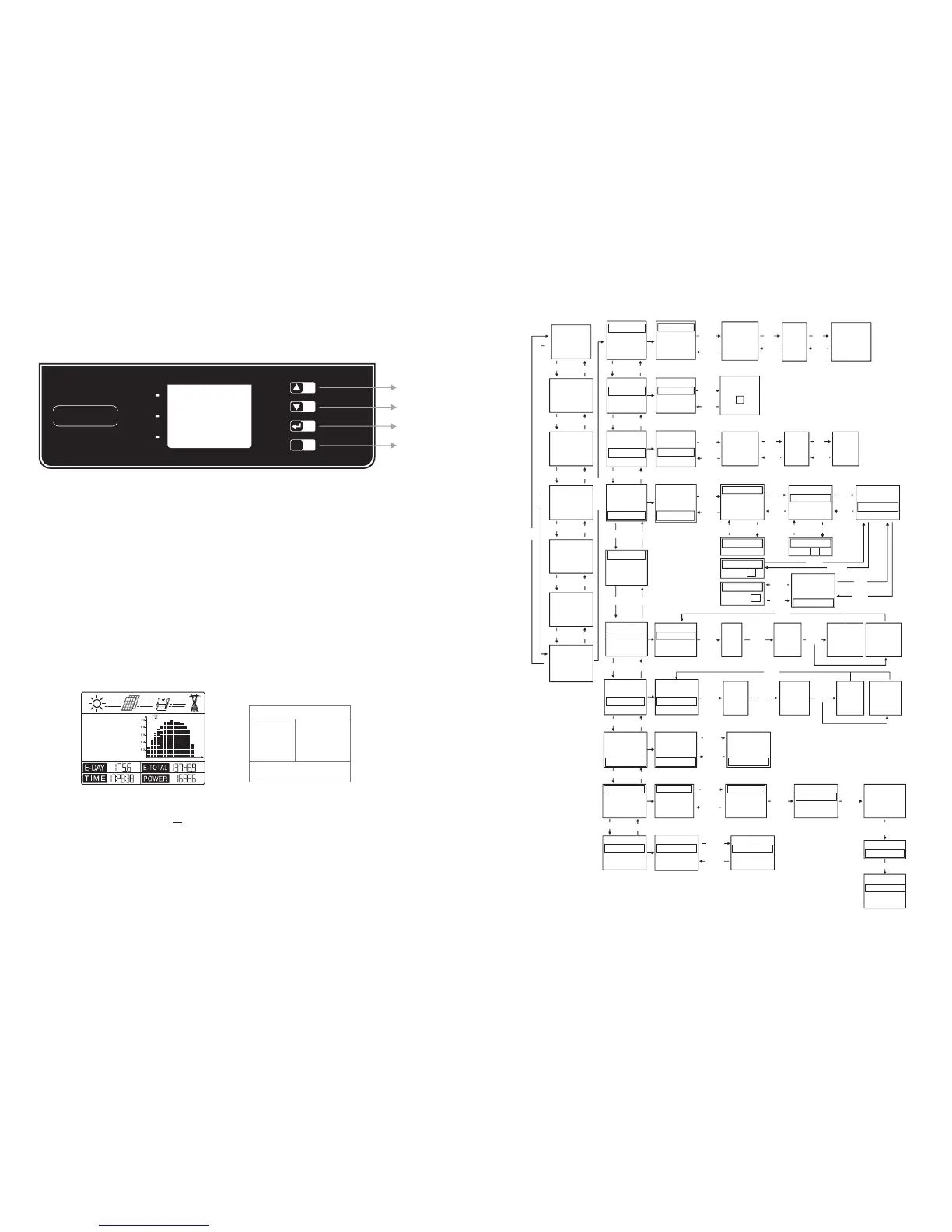
(1) The Figure of LCD display screen is shown as follow:
Area ①
Area ② Area ③
Area ④
Display area is divided as follows:
KWh
PM
W
KWh
N o r m a l
2 0 1 4 - 0 4 - 0 3
18
6
4
8
10
12
14
16
KWh
Set Safety Country :
If display shows 'Configure Safety', then long press (2S) the key to enter the second level menu. Short press to browse the safety
country list available. Choose suitable safety country according to the location of installation. The inverter will store the chosen
safety country after 20 seconds if no operation.
Enter
long press
Enter
long press
Enter
long press
Enter
long press
Enter
long press
Enter
long press
Enter
long press
Enter
long press
Enter long press
(2) Display area
Area①——Flow of Power Generated:
Area① indicates the flow of energy. Full line ( )between inverter and the grid means the grid is available but inverter is not yet feeding
power at the time. Flashing dashing lines (---) mean inverter is feeding power to grid. No line means grid is not available. Flashing dash
lines between the sun, modules and inverter means there is energy from the sun to modules and then from modules to inverter.
Area②——Status Information:
Area② displays inverter power generation status. Different inverter status like languages & time settings, error logs, historical power
information etc could all be switched and displayed here through button operations.
Area 2 has 3 levels of menu. Please refer to the diagram below.
 Loading...