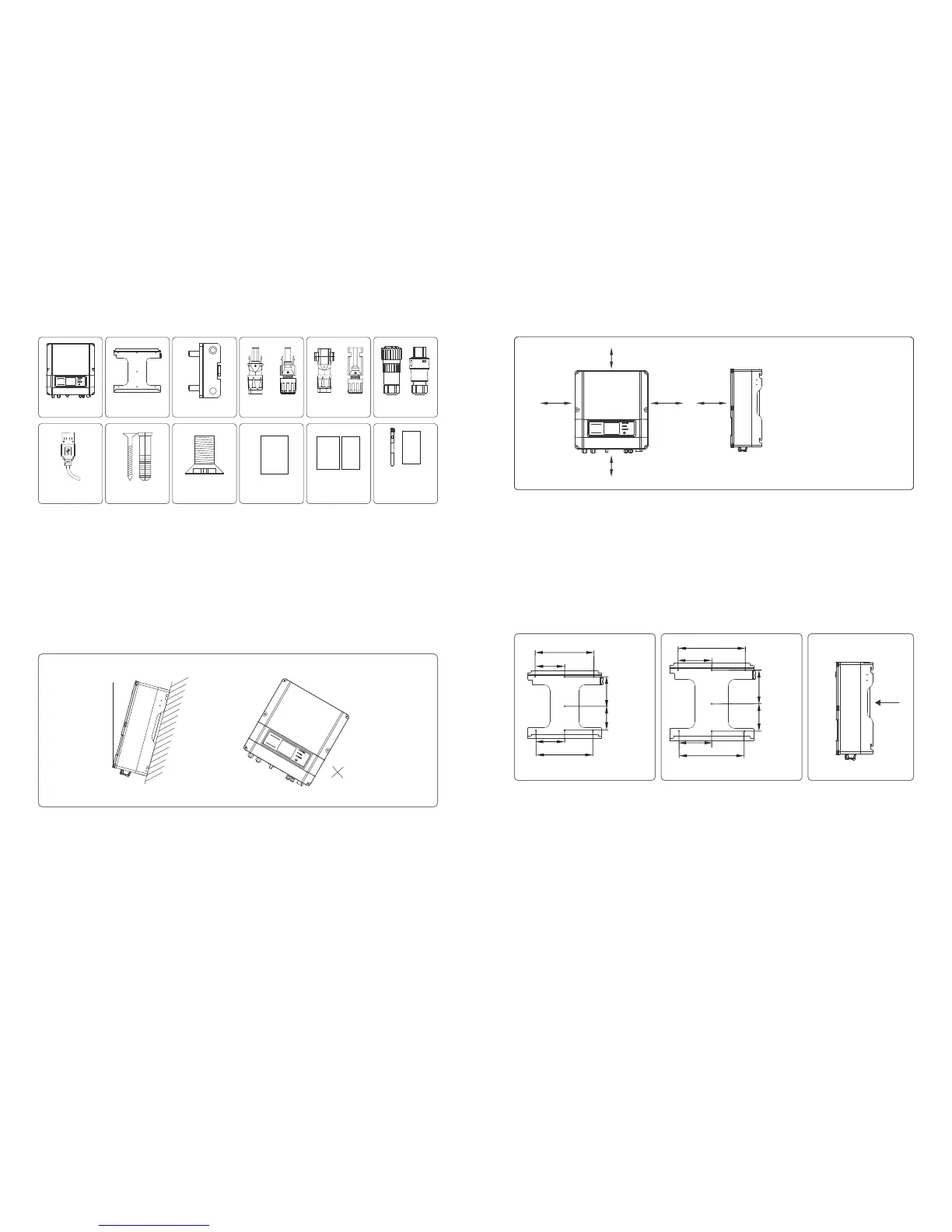
320mm
310mm
160mm
130mm
Figure 3.3.2-2 Figure 3.3.2-3
03 04
260mm
260mm
Figure 3.3.2-1
140mm
115mm
130mm
130mm
160mm
155mm
3.2.2 Package
Wall-mounted
Bracket×1
Lock Plate×1
Positive DC Plug×2*
Negative DC
Plug×2*
AC Plug×1
USB Data Cable×1
Expansion Bolts×7
Flat Head Screw×5
User Manual×1
Warranty card×1
Quick Installation
Guide×1
Antenna×1
WiFi Connection
Guide×1
(WiFi model only)
or
Inverter×1
*For GW1500-SS、GW2000-SS the number is 1.
or or
To allow dissipation of heat, and for convenience of dismantling, clearances around the inverter must be at least:
Groove
3.3.1 Selecting the installation location
The following must be considered when selecting the best location for an inverter:
●The mount and installation method must be appropriate for the inverter's weight and dimensions.
●The location must be well ventilated and sheltered from direct sunlight.
●The inverter must be installed vertical or with a backward tilt less than 15°. No sideways tilt is allowed. The connection
area must point downwards. Refer to Figure 3.3.1-1.
Upward ----------300mm
Downward- -------500mm
Front-------------300mm
Both sides---------200mm
Figure 3.3.1-1
200mm 300mm
3.3 Inverter Installation
MAX
15°
3.3.2 Mounting Procedure
(1) Use the wall-mounted bracket as a template and drill 7 holes in the wall, 10 mm in diameter and 80 mm deep. The inverter size of
1500W, 2000W, 3000W models can be referred to Figure 3.3.2-1, and the size of other models is as Figure3.3.2-2.
(2) Fix the wall mounting bracket on the wall using the expansion bolts in the accessories bag.
(3) Hold the inverter by the groove on the heat sink as Figure 3.3.2-3.
(4) Place the inverter on the wall-mounted bracket as illustrated in Figure3.3.2-4, 3.3.2-5, 3.3.2-6.
(5) Insert the lock plate pegs into the two holes in the heat-sink, then fix the inverter with a padlock and screw M3x8 as Figure
3.3.2-7, 3.3.2-8.
300mm
500mm
200mm
Figure 3.3.1-2
User
manual
Warranty
Card
Instruction of
Fast Installation
WiFi connection
configuration
 Loading...