09 10
4.2 User interface and use of the display
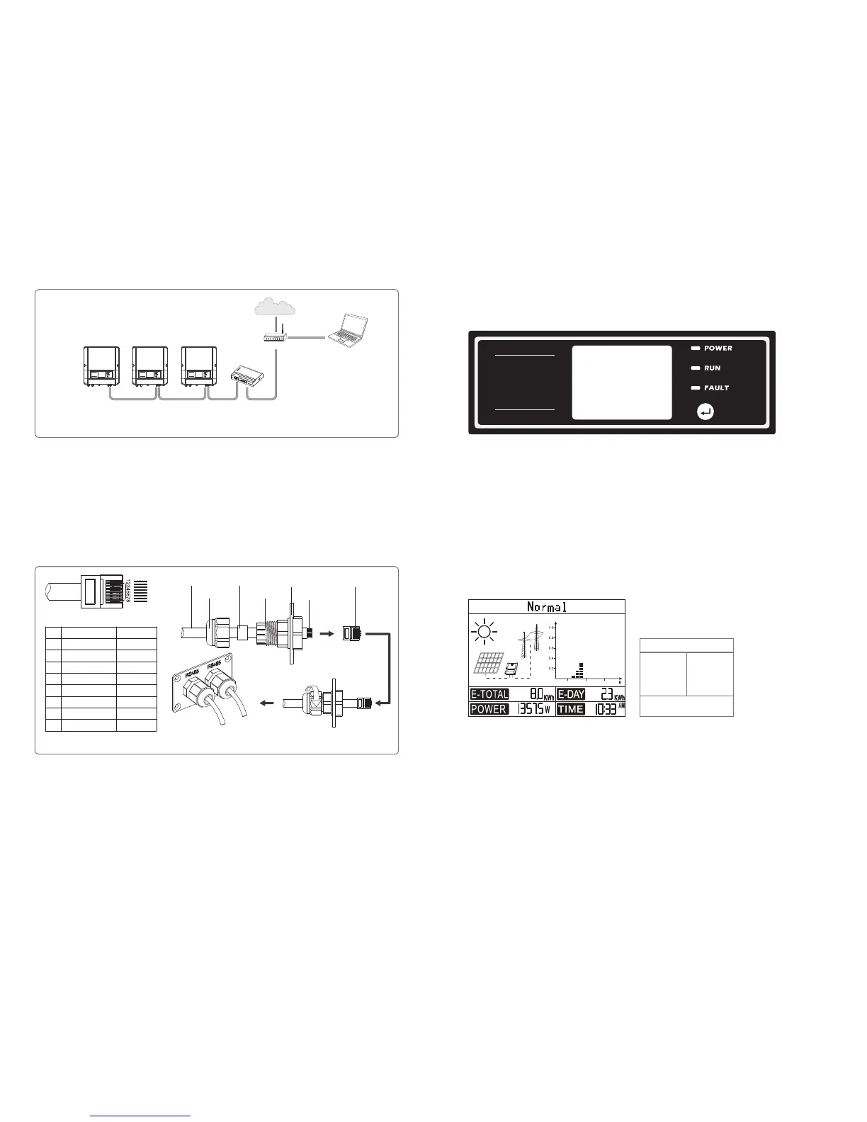
(1) A schematic of the display screen is shown as below:
(2) Display area
Area①---Working status information
● This area displays the status information. “Waiting” indicates the inverter is standby for power generation; “ Checking **S”
(checking time is based on safety, and varies from country to country) indicates the inverter is self-checking, counting down and
preparing for power generation. “Normal” indicates the inverter is generating power. If any condition of the system is abnormal,
the screen will display an error message. Refer to Table 4.3.
●Through key operation, the screen can display different information such as operation parameters and power generation status in
this area. There are two levels of menus, and the flow chart of first level menu is shown below:
Area①
Area② Area③
Area④
Display area is divided as follows:
18126
Indicator lights in Yellow/Green/Red correspondently refer to POWER/RUN/FAULT.
Yellow: Light on indicates the inverter is electrified. For WiFi models, Light flashes on 0.5sec off 0.5sec indicates the WiFi module
doesn’t connect to the WiFi router; Light flashed on 2.5sec off 2.5sec indicates the WiFi module connect to the WiFi router
but cannot receive data from Web Server; Always on indicates communication between Web Server is ok.
Green: Light on indicates the inverter is feeding power. Light off indicates the inverter is not generating power at the moment.
Red: Light on indicates abnormal conditions, while light off indicates normal condition.
4 System Operation
4.1 Indicator Lights
RS485 Communication
Board
Crystal Head
Tighten the screw
in clockwise direction
PIN
Color of the wire
Function
TX_RS485A
TX_RS485B
RX_RS485A
GND
GND
RX_RS485B
Reserved
Reserved
Orange and white
Orange
Green and white
Blue
Blue and white
Green
Brown and white
Brown
1
2
3
4
5
6
7
8
Screw cap
Single hole
seal ring
The insulator
Cables
Figure 3.4.4-2
RS485 waterproof assembly
(2) Connect the inverter to EzLogger with RS485 cable, and EzLogger to switch or router with CAT5E STP cable.
(1)Connection procedure:
●Remove the waterproof kit of RS485 cover with screwdriver.
●Remove the screw cap of the cable gland.
●Remove the one-hole sealing ring.
●Put the RS485 cable through the components in this order: screw cap, one-hole sealing ring, insulation body and sheet metal parts.
●Compress 8 cores of cable into the corresponding interface of crystal head. Refer to Figure 3.4.4-2.
●Connect the compressed crystal head to the communication interface of inverter.
●Fasten the RS485 waterproof kit to inverter.
●Fasten the screw cap of the cable gland.
3.4.5 WiFi Communication
The WiFi communication function is only applied to WiFi models, the detailed configuration instruction can be referred to WiFi
Configuration in the accessory box.
After configuration, please browse http://www.goodwe-power.com to create PV station.
INVERTER INVERTER INVERTER
RS485
EzLogger
RS485RS485
PCRouter
Internet
Figure 3.4.4-1
Reset
Reload
POWER
LINK
SPEED
RS485
USB
RCR
EzLogger
Cables
Set Safety Country :
If display shows 'Configure Safety', then long press (2S) the key to enter the second level menu. Short press to browse the safety
country available. Choose suitable safety country according to the location of installation. The inverter will store the chosen language
after 20 seconds of no operation.
 Loading...