Graham Corporation
13
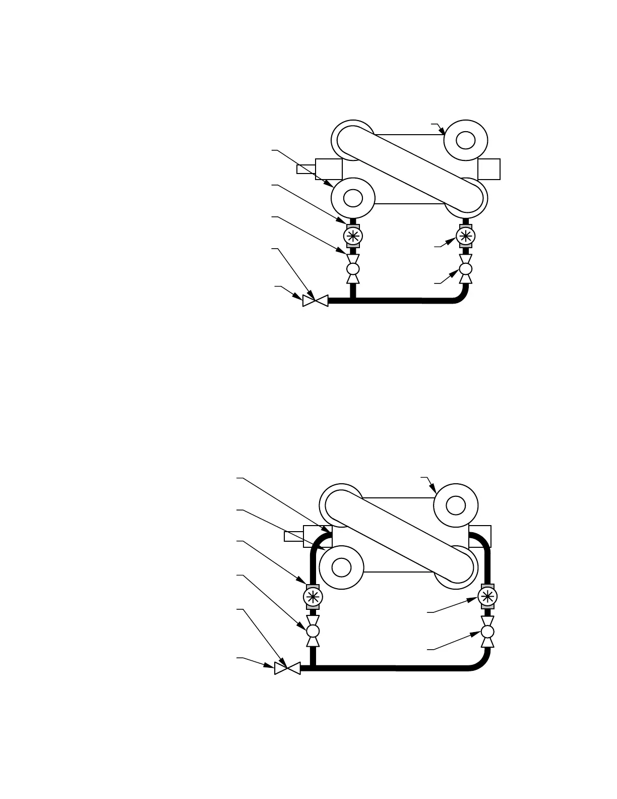
Size 40000 through size 80000 pumps will require coolant piping to both stuffing boxes.
Remove the seal flush harness and plug the unused connection(s). The optional piping
arrangement may be connected to either side of the pump. (See Figure 5)
Two Stage Pump
Shown
Regulating
Valve
Sight Flow
In
i
r
Regulating
Valve
Pump
Pump
Discharge
Sight Flow
In
i
r
Shaft Seal Coolant Inlet
at 10 PSI Above the
Discharge Pressure
Shut-Off
Figure 5 - Size 40000 through 80000 Optional Configuration
Size 90000 pumps are normally flushed internally. The coolant connections are at the ends
instead of at the side of the pump body. (See Figure 6) A plug has to be replaced with an M12
x 55 mm socket head cap screw at each end of the pump.
Figure 6 - Size 90000 Optional Configuration
Two Stage Pump
Shown
Plug
Screws
Shut-Off
Valve
Sight Flow
Indicator
Shaft Seal Coolant
Inlet at 10 PSI Above
the
Discharge
Pressure
Regulating
Valve
Sight Flow
Indicator
Regulating
Valve
Pump
Discharge
Pump
Suction
 Loading...