EasyManuals Logo
Home>Grandstream Networks>Intercom System>GDS3710

Grandstream Networks GDS3710 Configuration Guide

Grandstream Networks GDS3710
18 pages
To Next Page IconTo Next Page
To Previous Page IconTo Previous Page
Page #8 background imageLoading...
Page #8 background image
P a g e | 8
GDS3710 Input/output Alarms
Configuration Guide
J4
(Special)
2.0mm
1
GND
Wiegand Power
GND
Black
2
WG_D1_OUT
Wiegand Output
Signal
Orange
3
WG_D0_OUT
Brown
4
LED
Wiegand Output
LED Signal
Blue
5
WG_D1_IN
Wiegand Input
Signal
White
6
WG_D0_IN
Green
7
BEEP
Wiegand Output
BEEP Signal
Yellow
8
5V
Wiegand Power
Output
Red
Note:
Alarm IN and Alarm OUT are just electronic lock, they are either open to block the current or close to let
the current pass through, therefore a 3
rd
party power supply is needed to power the device connected to
the GDS3710 via Alarm IN or Alarm OUT.
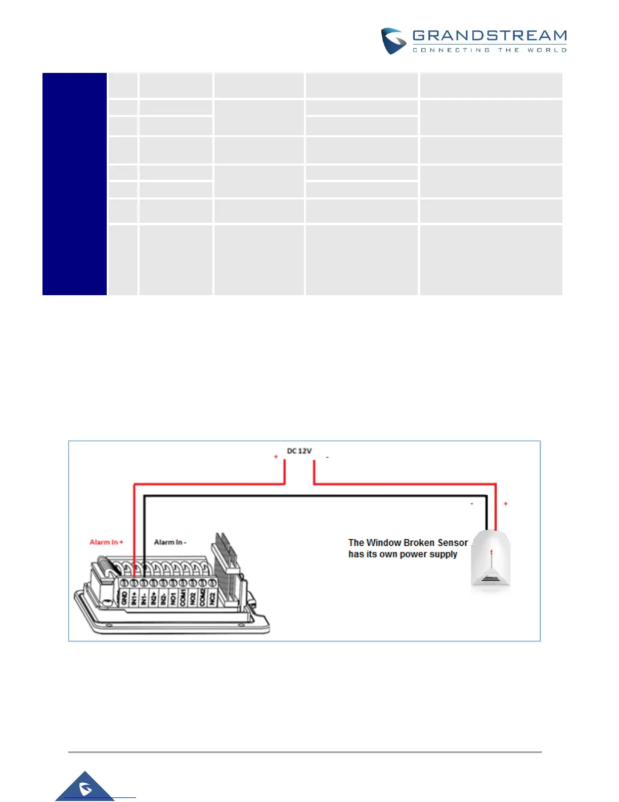
Alarm IN Connection Example
Connect Alarm (IN1+, IN1-) or (IN2+, IN2-) to appropriate wires in order to receive signal from the third
party device as shown below.
Figure 5: Alarm Input Example

Other manuals for Grandstream Networks GDS3710

Questions and Answers:

Question and Answer IconNeed help?

Do you have a question about the Grandstream Networks GDS3710 and is the answer not in the manual?

Grandstream Networks GDS3710 Specifications

General IconGeneral
BrandGrandstream Networks
ModelGDS3710
CategoryIntercom System
LanguageEnglish

Related product manuals