Unstirred water bath SAP, JBA, JBN Service Manual (Version 2.0) July 2014
31667 Page 4 of 23
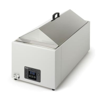
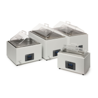
2 Product Description
2.1 SAP, JBA & JBN range
The ,SAP, JBA and JBN ranges of unstirred water baths are available in 8 tank sizes and in 2
mains voltage types.
The following table defines the models and serial numbers covered by this service manual.
Applicable Serial Nos (Date)
2
U*1332001 onwards (9
th
Aug 2013)
V*1332001 onwards (9
th
Aug 2013)
V*1427001 onwards (7
th
July 2014)
U*1332001 onwards (9
th
Aug 2013)
V*1332001 onwards (9
th
Aug 2013)
U*1336001 onwards (5
th
Sept 2013)
U*1332001 onwards (9
th
Aug 2013)
V*1336001 onwards (5
th
Sept 2013)
U*1336001 onwards (5
th
Sept 2013)
1. Where # denotes the bath size e.g. 5, 2S, 26 or D (dual bath 5&12)
2. Where * denotes an alphanumeric character dependent on bath type and size
2.2 Basic Description
All of the water baths follow the same construction method. A single piece painted case
contains mains inlet and wiring and the Control & Display PCB assembly. The tank, heater
and probe assembly is fitted into the case from the top and held in place by a number of small
bent tabs on the case which provide an interference grip. Heat resistant ties are used as a
secondary method to hold the tank to the case. A base plate with integral feet is attached to
the case bottom using M3 screws.
Major component parts are
Control & Display PCB assembly
Tank, heater and probe assembly
Mains inlet and wiring
Chassis assembly
Water in the bath is heated using a silicone mat heater that is glued to the underside of the
stainless steel tank. The heater mat includes one or more manual reset fixed over-
temperature cut-outs for safety that are bonded to the heater mat. The over-temperature cut-
out is wired to the heater using individual insulated wires. The control temperature probe is
mounted to the side of the tank and covered with an insulating patch. Power to the heater mat
is controlled by the Control & Display PCB assembly which is mounted to the case. The
control TRIAC protrudes from the Control & Display PCB assembly and is mounted to the
 Loading...