49
Combi V3, Combi Max and Vortex Combi models
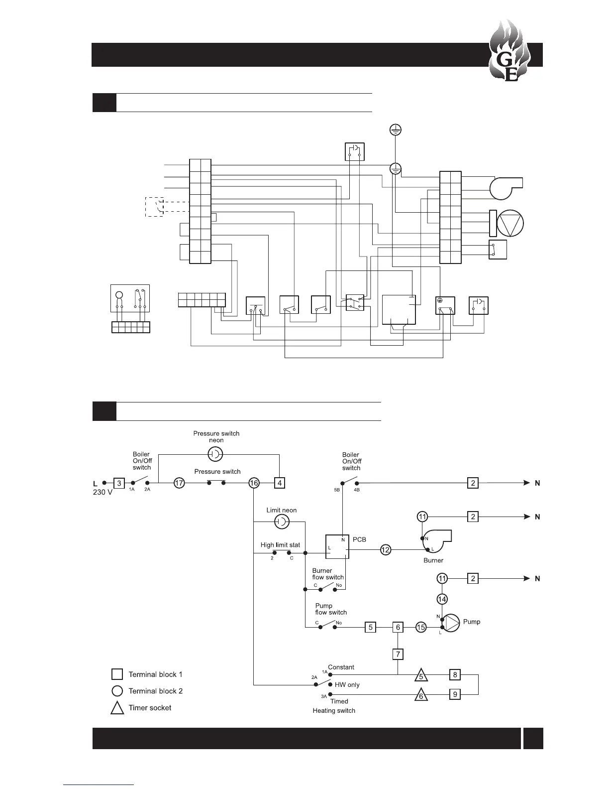
Functional flow wiring diagram - Combi V3 and Combi Max
12.2
1 2 3 4 5 6
M
RD
RD
RD
BL
Boiler
terminal
block 2
R/S link (red)
L
8
7
6
5
9
N
E
10
12
13
14
15
16
17
'Plug in' timer socket
1A
3A
2A
Heating
switch
Boiler
on/off
switch
c/w neon
C
2
G/Y
No
C
C
No
E N L
Pump
E
L
N
Burner
Pressure
switch
Live
Neutral
Burner live
Flow switch
N
E
L
4B
5B
1A
2A
Boiler terminal
block 2
G/Y
G/Y
G/Y
G/Y
BL
BL
BL
BL
BL
BL
BL
RD
RD
RD
RD
BL
RD
RD
RD
RD
RD
RD
RD
RD
OR
RD
Y
Y
BR
BR
BR
Electonic
PCB board
BLK
Y
OR
1
2
3
4
Chassis earth
to bolt in boiler
casing
Chassis earth
to bolt in boiler
casing
Pressure switch
neon (amber)
Overheat stat
neon (red)
Limit
stat
G/Y
RD
BL
Pump
flow
switch
Burner
flow
switch
1
234
5
6
Mains supply
(use 2 pole isolator
with power 'on'
indicator)
Frost
thermostat
(if fitted)
Note: Remove link
8 to 9 (yellow) if
timer is fitted
Note: If room thermostat is
fitted, remove link 6 to 7 (red)
and connect room thermostat
in its place
'Plug in' timer
24 hr mechanical
or 7 day timer
11
G/Y
OR
Y
Colour code: BLK Black, BL Blue, BR Brown, RD Red, Y Yellow G/Y Green/Yellow, OR Orange
12 - WIRING DIAGRAMS
Control panel wiring diagram - Combi V3 and Combi Max
12.1
 Loading...


