Combi V3, Combi Max and Vortex Combi models
50
4B
1A
5B
2A
OFF
3A
TIMED
CONSTANT
1A
2A
1
L
Burner live
Neutral
Live
Flow switch
11
A1
A2
6
7
10
9
Relay No.1
(bottom)
2
C
6
10
Relay No.2 (top)
9
17
20
21
22
19
18
L N E L N E
14
16
15
E
L
N
4B
5B
NC
NO
2
3
4
5
6
7
8
10
11
12
13
9
N
E
BL
RD
RD
RD
BLK
BR
BR
BLK
BL RD
OR
OR
BR
RD
OR OR
RD BLK BLK
BL
BLK
G/Y
BL
BL
G/Y
G/Y
BR
OR
OR
OR
OR
OR
OR
BL
BL
BL
BLK
BLK
RD
BR
G/Y
G/Y
6
54
1
2
3
Plug-in timer
socket
Heating
switch
Pressure
switch
Flow
switch
Boiler
terminal block
Mains supply
use 2 pole islolator
with power 'on' indicator
Remove link 8 to 9
(yellow) if timer is fitted
Frost thermostat
if fitted
If room thermostat is fitted
remove link 4 to 5 and connect
room thermostat in its place
Chassis earth
to bolt in panel
Chassis earth
to bolt in boiler
casing
Heating
pump
DHW
pump
Burner
Hot water
store
Pressure
switch neon
(amber)
Burner live
Neutral
Live
Flow switch
CH (adjustable)
PCB board
DHW (fixed)
PCB board
on bracket
Limit thermostat
Overheat thermostat
neon (red)
Boiler On/Off
switch with neon
OR
BL
Y
L
N
E
G/Y
A1
A2
OR
BLK
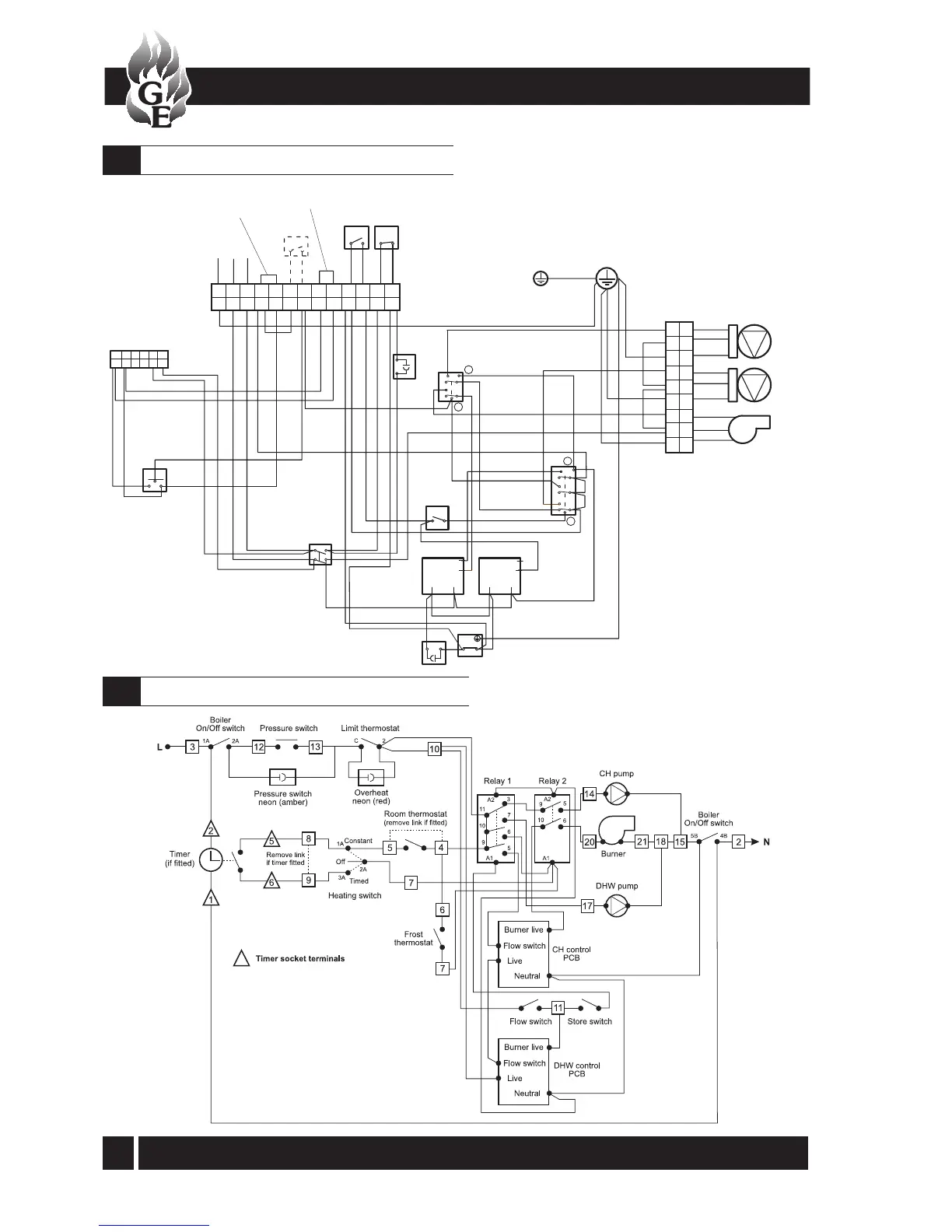
12 - WIRING DIAGRAMS
Control panel wiring diagram - Vortex Combi
12.3
Functional flow wiring diagram - Vortex Combi
12.4
Colour code:
BLK Black
BL Blue
BR Brown
RD Red
Y Yellow
G/Y Green/Yellow
OR Orange
 Loading...


