1/00 13
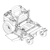
UNIT ASSEMBLY
Package Contents: Unit, Mower Deck and Literature Pack
Preparation Checklist
Refer to the Owner/Operator manual as required.
1. Unpack Unit - Remove shrink wrap and packaging
materials.
2. Remove Unit From Container - Open Bypass Valves
(dump valves) (See Moving the Unit with the Engine
Off in Operation).
Push unit from container onto a level surface. Close
the dump valves.
3. Tires - Adjust tire pressure for front tires;
20-25 PSI (138-172 kN/m
2
), rear tires; 12-15 PSI
(83-103 kN/m
2
).
4. Position and Attach Seat - Remove nuts from seat
studs in hood frame. Peel off paper backing from
foam tape (260Z). Lift and rotate seat onto hood
frame. Secure with nuts.
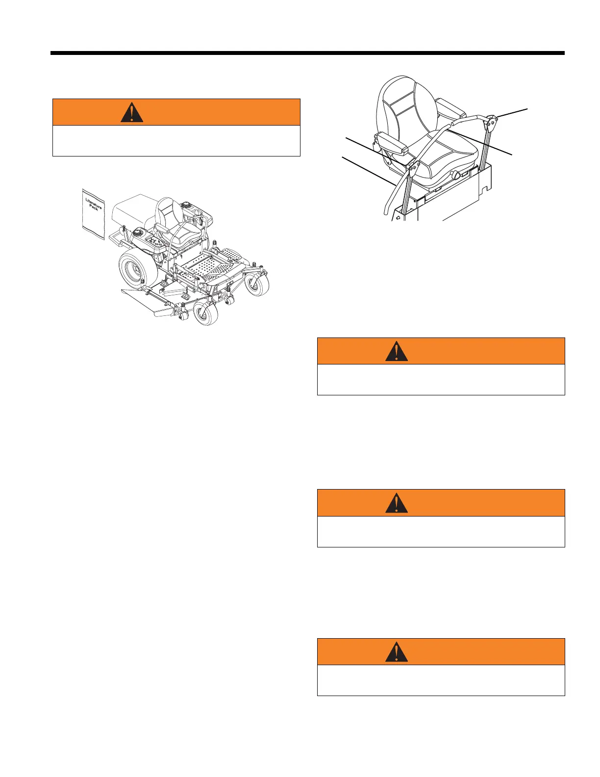
5. Position Steering Levers - Remove bolts and
spacers from steering rod. Flip the steering levers
up into operating position. Reinstall spacers, bolts
and nuts. Tighten hardware securely. See Figure 5.
6. Battery - Remove battery from unit, fill with
electrolyte and charge (See Battery in
Maintenance).
7. Check Engine Crankcase - To access engine, open
hood. Check and add oil if needed. See Engine
Manual for specifications. After service is
completed, close hood.
8. 60" & 72" Decks - Remove, reverse, and reinstall
deflector and mounting bracket.
9. Fill Engine Fuel Tank - Add clean fuel to the fuel
tank.
IMPORTANT: Refer to Engine Manual for fuel type.
10. Hardware - Check for loose hardware.
11. Check Safety Interlock System - Check to see that
the interlock system operates correctly.
12. Lubrication - Lubricate all fittings per maintenance
label under hood and check hydrostat oil level.
13. Level Deck - Check unit to assure deck level set at
factory has been maintained.
14. Check Function of all Controls - Ensure unit runs
and performs properly.
WARNING
Make all seat adjustments with unit stationary, parking
brake on and engine shut off.
Figure 4
DF0090
WARNING
DEFLECTOR must pivot freely. DO NOT over tighten
the pivot bolts.
WARNING
FAILURE OF INTERLOCK, together with improper
operation can result in severe personal injury.
WARNING
FAILURE OF CONTROLS could result in death or
serious injury.
Figure 5
1. Steering Lever in
Shipping Position
2. Spacers and
Hardware
3. Steering Lever in
Operation Position
1
2
3
2
OF3140
SECTION 3: ASSEMBLY
 Loading...