Multi Variable Air Conditioners Ducted Type Indoor Unit
18
downstream IDU of the communication bus (terminal D1 and D2), as shown in fig 5.3.2,
terminal resistor is provided with each ODU.
5.4 Connect Communication Wire of Wired Controller
(1) Open electric box cover of indoor unit.
(2) Let the communication wire go through the rubber ring.
(3) Connect the communication wire to terminal H1 and H2 of indoor 4-bit wiring board.
(4) Fix the communication wire with wire clip on the electric box.
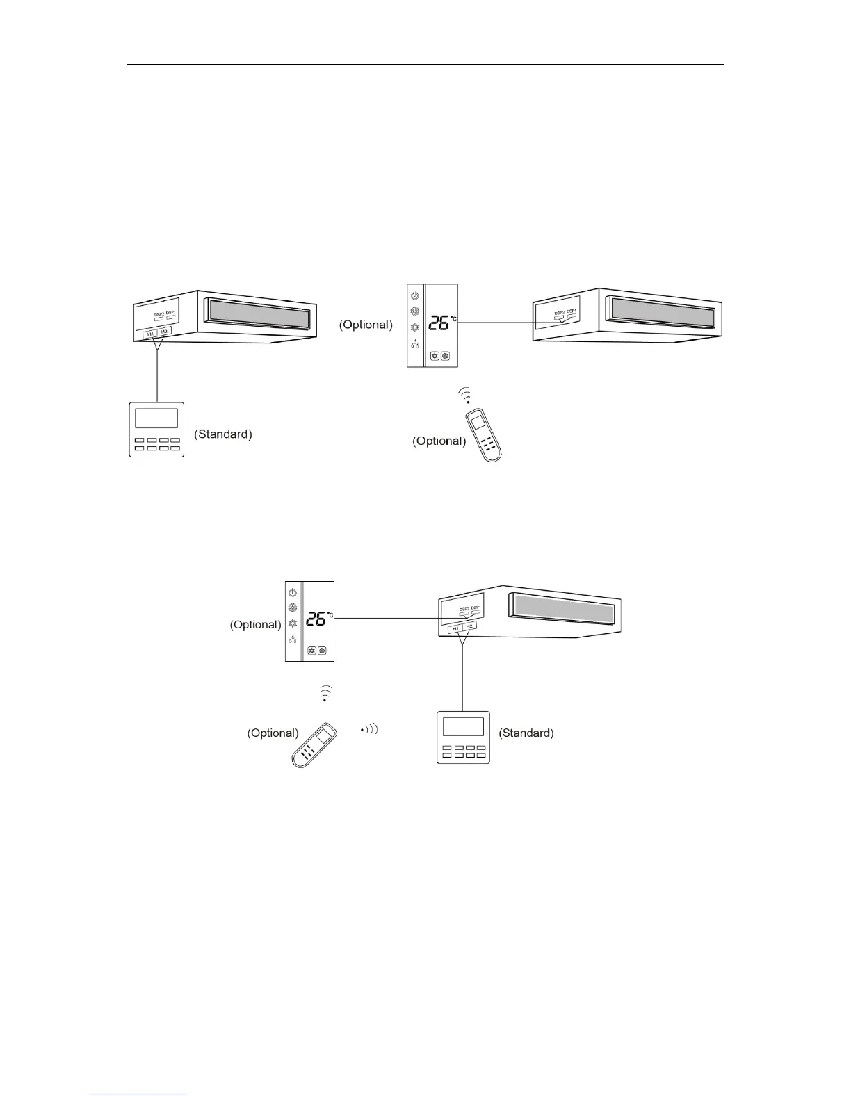
(5) Wiring instructions of remote receiving light board and wired controller:
1) Fig 5.4.1 shows the installation of wired controller.
Fig 5.4.1 Fig 5.4.2
2) Fig 5.4.2 shows the installation of remote controller.
3) Wired controller and receiving light board can be installed at the same time. When
operating through a remote controller, both wired controller and the receiving light
board can receive the signals, as shown in Fig 5.4.3.
Fig 5.4.3
5.5 Illuminate for Connection of Wired Controller and Indoor Units Network
(1) Communication wire of indoor unit and outdoor unit (or indoor unit) is connected to D1,
D2.
(2) Wired controller is connected to H1, H2.
(3) One indoor unit can connect two wired controllers that must be set as master one and
slave one.
(4) One wired controller can control 16 indoor units in maximum at the same time. (As shown
in fig5.5).
 Loading...