Instruction of the GMV D.C. inverter
3
conditioner unit is generating heats indoors, the condensate water may flow from the base of
outdoor unit. When outdoor air is below 0 (32 ), the condensate water will be frozen. Take care
that the installation of outdoor unit shall not affect the heat radiation of the unit.
Caution!
Installation at following positions might cause trouble to the air conditioner unit. If unavoidable,
please contact Gree Authorized Service Center.
① .
A place full of machine oil;
② .
A region with saline-sodic soil near the sea;
③ .
A place with sulphide gases (such as sulphur spring);
④ .
A place with high frequency facilities, such as radio equipment, electric welder or medical
equipment;
⑤ .
An environment with special conditions.
2.4 Cable Layout
Carry out installation in accordance with the state line layout rules.
The power supply must be of rated voltage of the unit and special electrical line for air-
conditioning.
Please do not pull the power supply line violently.
All electrical installation shall be carried out by professional technicians in accordance with
the local laws and regulations
The diameter of exible power cable must be large enough; damaged exible power cable
and connection cable must be replaced by exible cables of such special purpose.
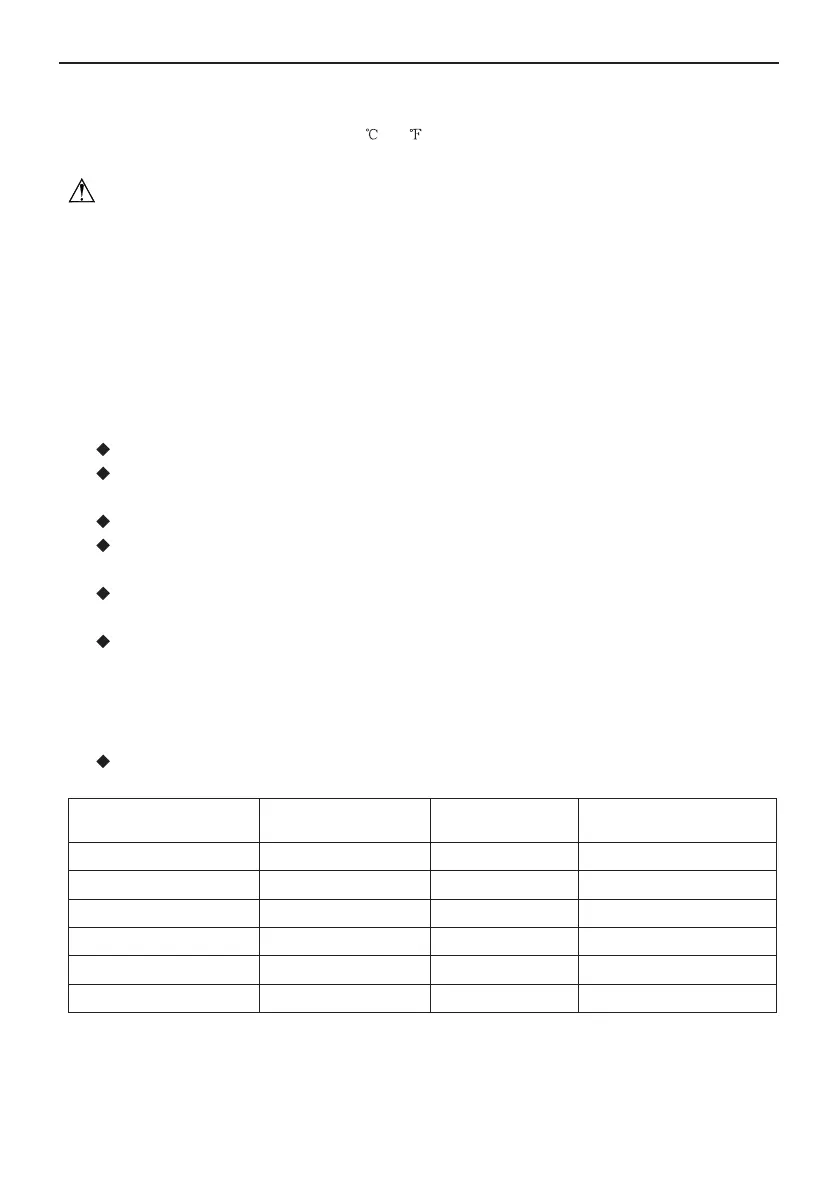
Ensure safe grounding and the grounding wire shall be connected with the special grounding
equipment of the building and must be installed by professional technicians. In the xed line there
must be an electrical leakage protection switch and an air switch with sufficient capacity (refer
to the following table). The air switch shall also have the magnetic tripping and thermal tripping
functions to achieve protection of both short-circuit and overload.
An air switch having a contact separation of at least 3mm in all poles should be xed in xed
wiring.
Model power supply
Switch of capacity
for air
Suggested conducting
line(*area of section)
GMV-Pd100W/NaB-K 220-240V~,50Hz 32 3×4.0
GMV-Pd120W/NaB-K 220-240V~,50Hz 32 3×4.0
GMV-Pd140W/NaB-K 220-240V~,50Hz 40 3×6.0
GMV-Pd160W/NaB-K 220-240V~,50Hz 40 3×6.0
GMV-Pd140W/NaB-M 380-415V 3N~ , 50Hz 16 5×1.5
GMV-Pd160W/NaB-M 380-415V 3N~ , 50Hz 16 5×1.5
NOTE:
① .
The specications of the breaker and power cable listed in the table above are determined
based on the maximum power (maximum amps) of the unit.
② .
The specications of the power cable listed in the table above are applied to the conduit-
 Loading...