U-Match Series DC Inverter Service Manual
40
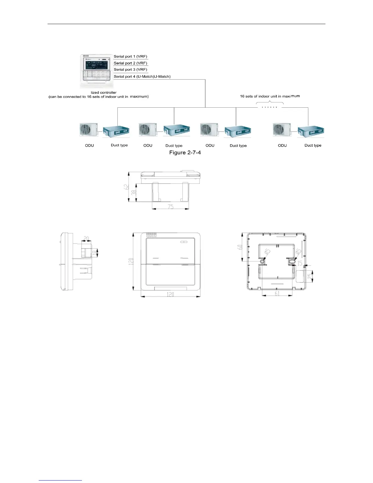
7.1.4.3 Network Topology
Network Connection of the Smart Zone Controller
7.1.4.4 Dimensions
Figure 2-7-5
7.2 Additional Special Functions
7.2.1 Door control function
Door control function is available for this series. In order to achieve this function, please select the
door control accessories from Gree.
(1) Interface instructions
1) The interface printing is DOOR-C and the type is B2B-XH-B. The wires of door control
accessories must be connected to this interface;
2) Electrical characteristic: none;
3) Working principle: when the card is inserted, this interface is short-circuited; when the card is
not inserted, this interface is cut off;
Connect the door control detection port of indoor mainboard with the interface of door control board
(CN1 in the following Figure); connect the door control signal to the door control signal input port (X1 and
X2 in the following Figure). X1 is AC 220V signal input and X2 is DC +5V to 24V. You can only choose
 Loading...