19
Technical Information
Service Manual
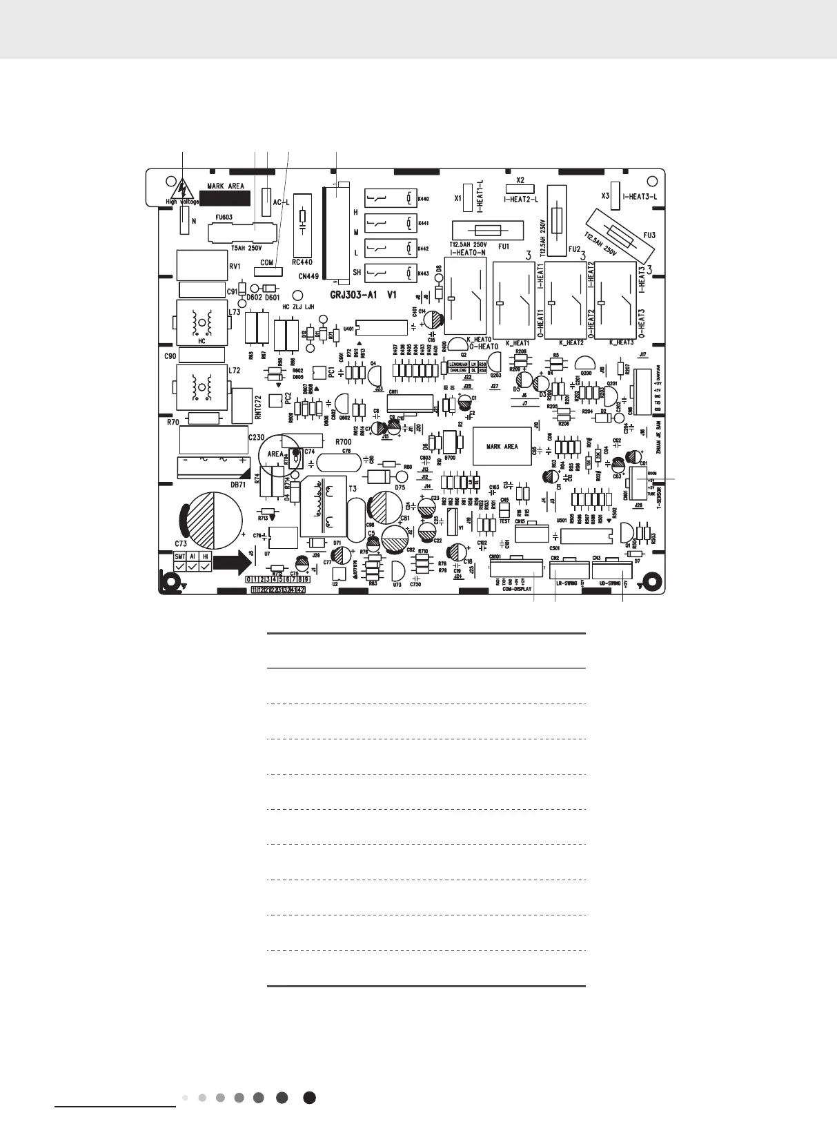
5.2 PCB Printed Diagram
Indoor Unit
No. Name
1 Neutral wire
2 Fuse
3 Live wire
4
Communication terminal
(with outdoor unit)
5 Needle stand for indoor fan
6 Interface of temperature sensor
7 Up&down swing interface sensor
8 Left&right swing interface sensor
9 Connection with display board sensor
1 Neutral wire
2 Fuse
3
Live wire
4
Communication terminal
(with outdoor unit)
5
Needle stand for indoor fan
6
7
8
9
Interface of temperature
sensor
Up&down swing interface
sensor
Left&right swing interface
sensor
Connection with display board
sensor
12
34 5
6
789

 Loading...