20
Technical Information
Service Manual
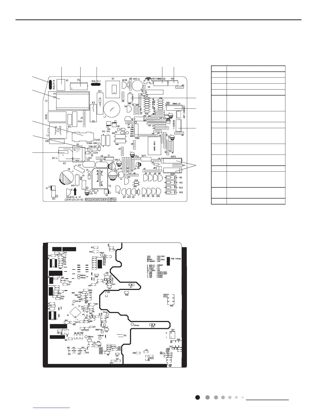
5.2 PCB Printed Diagram
Indoor Unit
● Top view
● Bottom view
No. Name
1 Power supply live wire
2 Communication wire
3 Fuse
4 Indoor fan driven capacitor
5
Neutral wire interface of cold
plasma(only for the model
with this function)
6
Neutral wire interface of
power supply
7 Interface of PG motor
8
Live wire interface of cold
plasma(only for the model
with this function)
9
Interface of up & down swing
motor
10
Interface of indoor fan
feedback
11 Jumper cap
12
Interface of left & right
motor(only for the model
with this function)
13
Interface of temperature
sensor
14 Interface of display
1
2
3
4
5
6 7
8 9
10
11
12
13
14

 Loading...