41
DC Inverter Multi VRF System II
Service Manual
INSTALLATION
1.Engineering Installation Preparation and Notice
1.1 Installation notice
Personnel and property safety are highly concerned during the entire installation process. Installation implementation must abide by
relevant national safety regulations to ensure personnel and property safety.
All personnel involved in the installation must attend safety education courses and pass corresponding safety examinations before
installation. Only qualified personnel can attend the installation. Relevant personnel must be held responsible for any violation of the
regulation.
1.2 Installation key points and importance
VRF air conditioning systems use refrigerant, instead of other agent, to directly evaporate to carry out the system heat. High level
of pipe cleanness and dryness is required in the system. Since various pipes need to be prepared and laid out onsite, carelessness or
maloperation during installation may leave impurities, water, or dust inside refrigerant pipes. If the design fails to meet the requirement,
various problems may occur in the system or even lead to system breakdown.
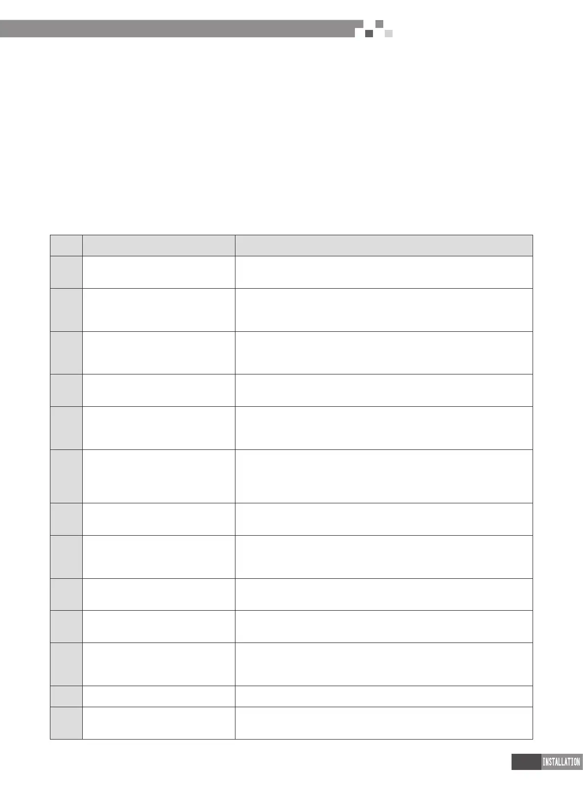
Problems that usually occur during installation are as follows:
No. Installation Problem Possible Consequence
1
Dust or impurities enter into the
refrigeration system.
Pipes are more likely to be blocked; air conditioning performance is reduced;
compressor wear is increased or even hinder the normal operation of the system and
burn the compressor.
2
Nitrogen is not lled into the refrigerant
pipe or insufcient Nitrogen is lled before
welding.
Pipes are more likely to be blocked; air conditioning performance is reduced;
compressor wear is increased or even hinder the normal operation of the system and
burn the compressor.
3
The vacuum degree in the refrigerant pipe
is insufcient.
The refrigeration performance is reduced. The system fails to keep normal operation
due to frequent protection measures. When the problem getting serious, compressor
and other major components can be damaged.
4
Water enters into the refrigeration system.
Copper plating may appear on the compressor and reduce the compressor efciency
with abnormal noise generated; failures may occur in the system due to ice plug.
5 The refrigerant pipe specications do not
meet the conguration requirements.
Smaller conguration specications can increase the system pipe resistance and
affect the cooling performance; larger conguration specications are waste of
materials and can also reduce the cooling performance.
6 Refrigerant pipe is blocked.
The cooling performance is reduced; in certain cases, it may cause long-term
compressor operating under overheat conditions; the lubricating effect can be
affected and the compressor may be burnt if impurities were mixed with the
lubricating oil.
7
Refrigerant pipe exceeds the limit.
The loss in pipe is considerable and the unit energy efciency decreases, which are
harmful for long-term running of the system.
8
Incorrect amount of refrigerant is lled.
The system cannot correctly control the ow allocation; the compressor may be
operating under over-heating environment or running when the refrigerant ows back
to the compressor.
9 The refrigerant pipe leaks.
Insufcient refrigerant circulating in the system decreases the cooling performance
of the air conditioner. Long-term operation under such circumstance may cause an
overheating compressor or even damage the compressor.
10 Water drainage from the condensate water
pipe is not smooth.
Residual water in IDUs can affect the normal operation of the system. The possible
water leakage can damage the IDU's decoration.
11
The ratio of slop for condensate water pipe
is insufcient or the condensate water pipe
is incorrectly connected.
Reverse slop or inconsistent connection of condensate water pipe can hinder the
smooth drainage and cause leakage of the IDU.
12
The air channel is improperly xed.
The air channel will deform; vibration and noise occur during unit operating.
13 The guide vane of air channel is not
reasonably manufactured.
Uneven air quantity allocation reduces the overall performance of the air conditioner.
 Loading...