70
DC Inverter Multi VRF System II
Service Manual
5 Removal of Parts
5.1 Key parts
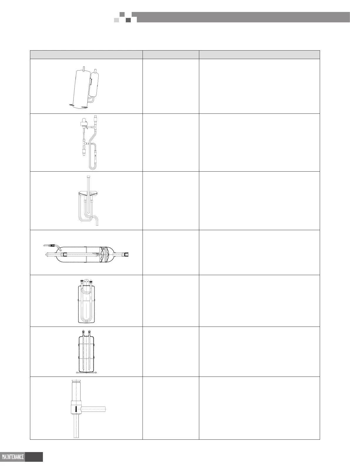
Photo Name Function
compressor
Core part of air conditioning system. It sucks low
temperature and low pressure gas, compress it to
high temperature and high pressure gas, and then
discharge it.
Electronic expansion
valve
Throttling device. It transforms high pressure
refrigerant liquid into low pressure steam.
4-way valve It changes the ow direction of refrigerant for switching
between cooling and heating.
Oil separator
It stays between discharge outlet of compressor and
inlet of condenser. It used for separating the lubricant
oil of compressor when the high temperature and
high pressure refrigerant gas is discharged from the
compressor.
Vapour liquid separator
It stays between outlet of evaporator and suction ouitlet
of compressor. It used for separating low temperature
and low pressure refrigerant.
High pressure liquid
storage tank
It used for storing the superuous high pressure
refrigerant liquid during cooling process.
Solenoid valve
Control to the high-voltage current: open upon power
on; close upon power off
 Loading...