69
DC Inverter Multi VRF System II
Service Manual
4.2 Main electric parts
Name Photo Function introduction
Filter plate
It main effect is to eliminate the interference of power for
protecting unit’s anti-interference capability and prevent the
interference to other electric appliances.
IPM Module
There are three complemental IGBT tube inside the IPM
module. They are controlled by PWM wave and then bring
the pressure of DC bus bar to different stator windings of
compressor at different stage, and then generate current on
the stator. Meanwhile, magnetic eld will be generated on the
stator winding, and push the operation of rotor and then drive
compressor to operate.
PFC module
Four diodes and two MOS pipe are intergrated inside the
PFC module. It will transform AC input power into DC power.
Meanwhile, MOS pipe is controlled by PWM wave. Pressure
will be increased by induction.
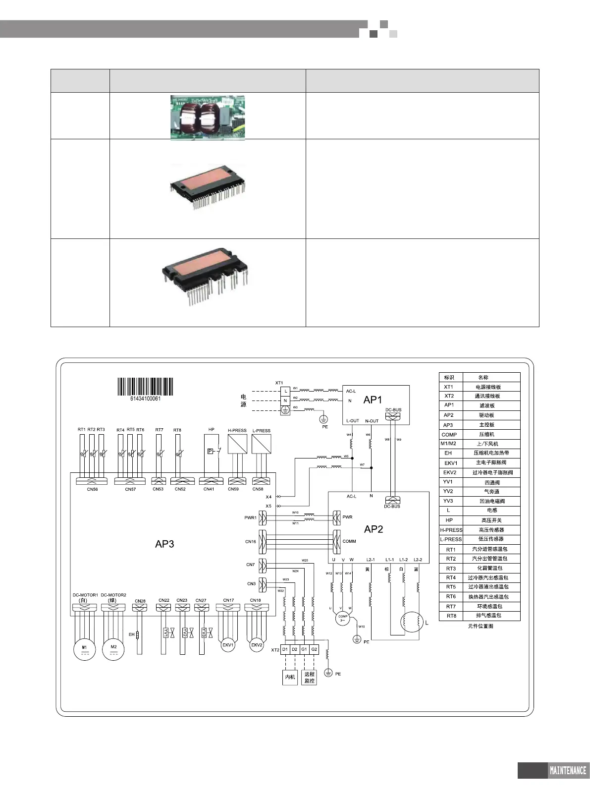
4.3Circuit diagram
Circuit diagram of outdoor unit
 Loading...