4
DC Inverter Multi VRF System II
Service Manual
PRODUCT
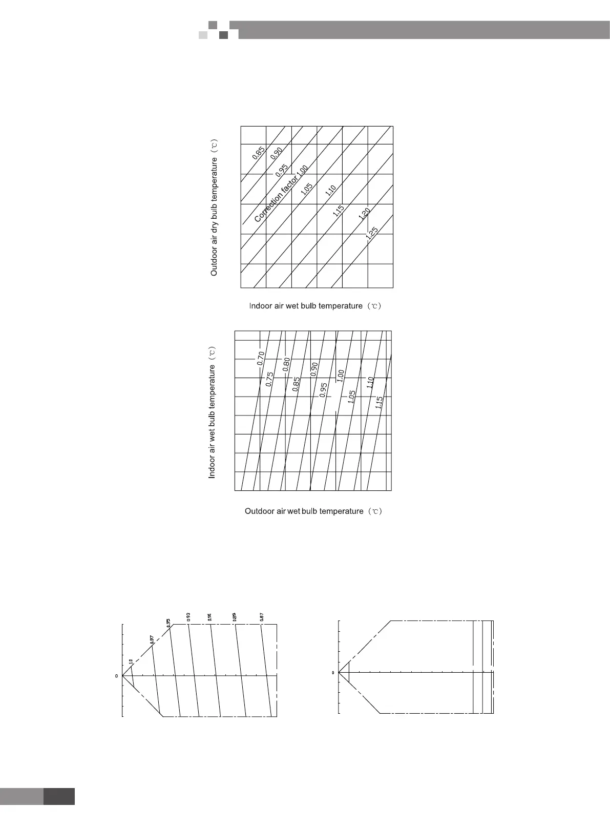
5 PRODUCT CAPACITY CORRECTION
5.1 Correction factor of indoor and outdoor temperature
(1) Correction factor of cooling capacity
20
16
14 16 18 20 22 24 26
25
30
35
40
43
(2) Correction factor of heating capacity
-15 -10 -5 0 5 10 15 16
12
10
14
16
22
18
20
24
26
27
5.2 Correction factor of pipe length and height difference
(1) Symbol description:
Hp: Height difference in case indoor unit is below outdoor unit (m);
Hm: Height difference in case indoor unit is above outdoor unit (m);
L: Length of one-way equivalent pipe.
(2) Below table shows the capacity variance ratio for 100% full load in standard working condition (thermostat setting is 16℃ for cooling
and 30
o
C for heating).
Hm(m)
40
20
30
10
Hp(m)
20
10
10
20 30
30
40
50
6040 50 70 80 11090 1001 20 150
1.0
0.99
0.97
0.95
L(m)
1301 40
Hm(m)
40
20
30
10
Hp(m)
20
10
10
20 30
30
40
50
6040 50 70 80 11 090 1001 20 150
L(m)
1301 40
Variance ratio of heating capacity Variance ratio of heating capacity
 Loading...