Home
Gree
Air Conditioner
UML600H/A-MP
Gree UML600H/A-MP User Manual
4
of 1
of 1 rating
121 pages
Give review
Manual
Specs
To Next Page
To Next Page
To Previous Page
To Previous Page
Loading...
GREE
D
uct ty
pe Ducted Type Split
Air
-
Conditioner Units
22
3
.4.1.
2
Ins
tallati
on
Process
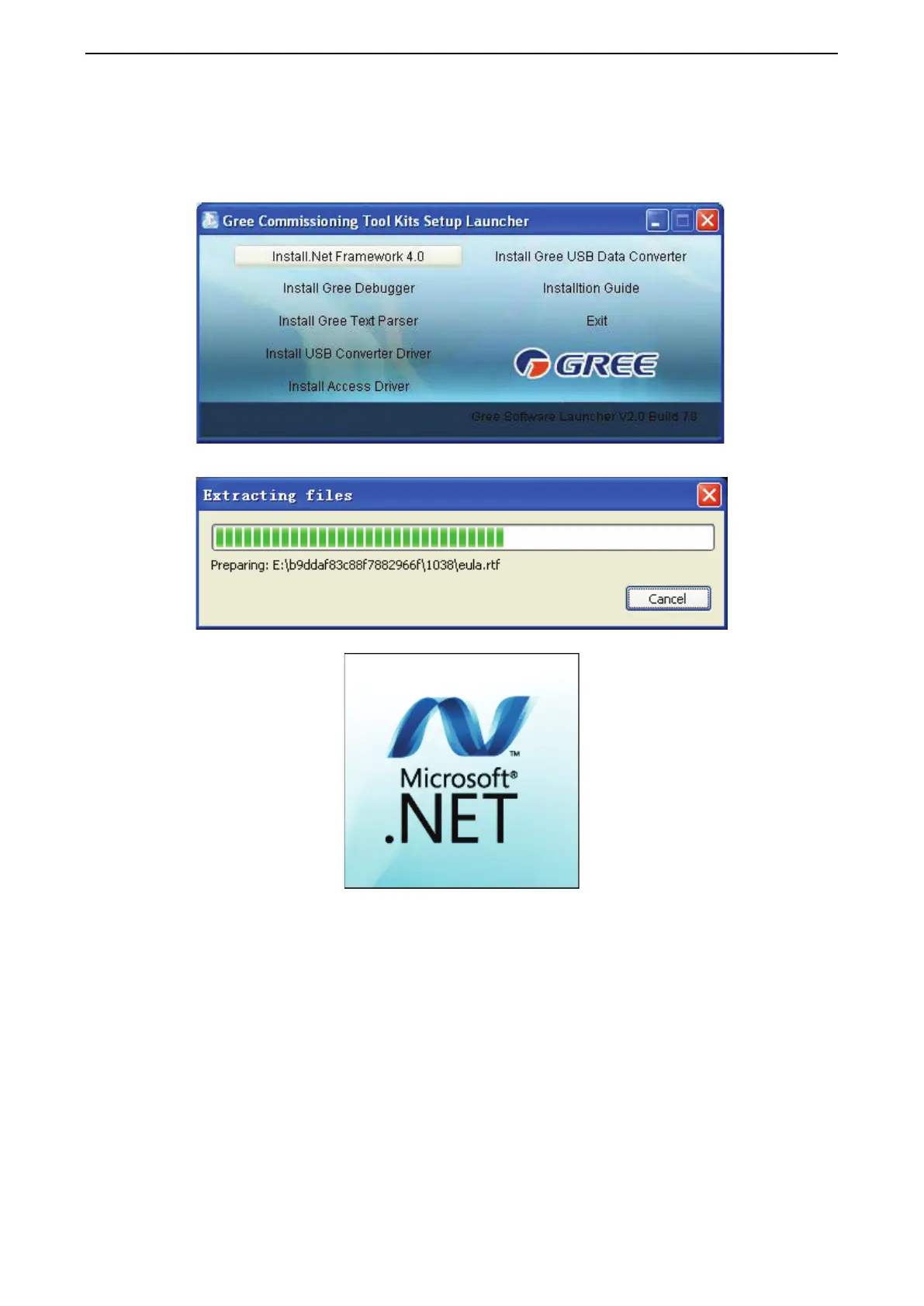
(1)
Install .Net
Framewor
k 4.0
1)
If
yo
ur computer
has installed .
N
et Fra
mework 4.0
or versions abov
e, there’
s no need to
install aga
in. Otherwise, c
lick “Instal
l .Net Fra
mework 4.0”.
2)
Extracting f
iles
21
23
Table of Contents
Default Chapter
2
Table of Contents
2
Product
4
Product List
5
Nomenclature
6
Outdoor
6
Indoor
6
Specifications
7
Control
9
Wired Controller
10
Control Panel
10
Appearance of Wired Controller
10
LED Graphics of Wired Controller
10
Symbols
11
Installation and Removal
12
Button Graphics
12
Parts of Wired Controller
12
Installation of Wired Controller
13
Connection of Communication Cord
14
Removal of Wired Controller
14
One Wired Controller Controls One Indoor Unit
14
Remote Controller YAP1F
15
Button Name and Function Introduction
15
Monitoring Software
16
Function Introduction
16
Connection of Computer and Units
16
List of Parts
16
Gree USB Data Converter
17
Functions Introduction
17
Operation Instruction
18
Communication Board
18
Installation Notice
18
Communication Cord
19
USB Wire
19
Board Connection Wire
19
Software Introduction
19
Software Installation
20
Installation Requirements
20
Computer Configuration
20
Real-Time Control
20
Installation Flowchart
21
Installation Process
22
Install .Net Framework 4.0
22
Install USB Converter Driver
30
Install Gree USB Data Converter
30
Data Monitoring
35
Project Debugging
40
Control Units
42
Other Functions
45
Capture Screen
45
Search for Database Folder
46
Conversion of Pressure Value
47
Database Saving of Multiple Systems
47
Change Database Saving Path and Rebuild Database
48
Usage of USB Converter
50
Usage of Converter
50
Usage of Converter Configuring Software
53
Baud Rate Look-Up Table of CAN Interface (Unit: Bps)
54
Installation
56
Engineering Installation Preparation and Notice
57
Installation Key Points and Importance
57
Installation Materials Selection
57
Refrigerant Piping
57
Condensate Water Pipe
58
Insulation Material
58
Communication Cable and Control Cable
59
Power Cable
59
Hanger Rod and Support
59
Installation of Indoor Unit
60
Outline and Installation Dimension
60
Installation Space
60
External Static Pressure Setting and Reading(UMD400PH/A-M(P))
61
External Static Pressure Reading
62
Installation Notice
62
Selection of Air Switch and Power Cord
63
Installation of Outdoor Unit
63
Check before Installation
63
Selection of Installation Site
63
Carrying and Installing Outdoor Unit
63
Installation Notices
63
Fixing and Damping of Unit
64
Outline Dimension and Position of Installation Hole
64
Installation Space Requirement
66
Pipeline Design of Refrigerant
67
Notices for Pipeline Design
67
Allowable Length and Fall for Refrigerant Pipe in IDU and ODU
68
Design of Oil Loop
68
Purpose of Setting Oil Loop
68
Principle of Setting Oil Loop
68
Installation of Drain Pipe
69
Installing the Drain Pipes
69
3-Way Connection of Drainage Pipe Joint
70
Connection of Drain Elbow
70
Connection of Horizontal Pipe
70
Testing of Drain Piping
71
Electrical Installation
71
Debugging&Maintenance
72
Debugging Flow Chart
73
Preparation before Debugging
73
Safety Notice
73
Debugging Process
76
Confirm before Commissioning Description
76
Main Board of ODU for Debugging
76
Basic Operation of Project Debugging
77
Start Project Debugging
77
Exit Project Debugging
77
Complete Project Debugging
77
Description of each Stage of Debugging Progress
78
Function Setting(UMD400PH/A-M(P))
80
Function Setting of Outdoor Unit
80
Quiet Function of Outdoor Unit
80
Unit Cooling and Heating Function Setting
81
Mandatory Defrosting Operation
81
Energy Conservation Operation Setting
81
Troubleshooting
82
Reset Factory Setting
82
“A0” Debugging for Unit
84
“A3” Defrosting
84
“A4” Oil Return
85
“A6” Cooling/Heating Function Setting
85
“A7” Quiet Mode Setting
85
“AH” Heating
85
“AU” Remote Emergency Stop
86
“Ab” Emergency Stop
86
“AF” Fan Blow
86
“AJ” Cleaning Alarm for Filter
86
“B1” Malfunction of Outdoor Ambient Temperature Sensor
87
“B2” Malfunction of Defrosting Temperature Sensor 1
88
“B9” Malfunction of Gas Exit Temperature Sensor for Heat Exchanger
89
Judgment Condition and Method for the Fault
89
“C6” Alarming Due to Wrong Quantity of Outdoor Unit
91
“CC” Malfunction of no Main Control Unit
91
“D6” Outlet Pipe Temperature Sensor Error
93
“DC” Capacity DIP Switch Setting Error
94
“Db” Project Debugging
94
“E1” High Pressure Protection
94
“E3” System Low Pressure Protection
95
Detect Compressor Discharge Temperature through
98
“J7” Air-Mixing Protection for 4-Way Valve
99
“J7” 4-Way Valve Protection
100
“L1” Indoor Fan Protection
100
“L5” Freeze Protection
101
“N0” Energy Conservation Setting for Operation
101
“N4” Limit Setting for the Maximum Output Capacity
101
“N6” Malfunction Inquiry
101
“N7” Parameters Inquiry
102
“N8” Engineering Series Number Inquiry for Indoor Unit
102
“Na” Quantity Inquiry Status of Online IDU
102
“Nh” Heating Only Model
102
“Nc” Cooling Only Model
103
“Ne” Negative Code
103
“Nf” Fan Model
103
“P0” Malfunction Driven Board for Compressor
103
“P2” Power Voltage Protection for the Driven Board of Compressor
104
“P3” Reset Protection for the Driven Module of Compressor
104
Compressor Driver Board Error
105
“P5” Overcurent Protection for Inverter Compressor
105
“P6” Driven IPM Module Protection for Compressor
106
Driven Board of Compressor Is Faulted
107
“P8” Overheating Protection for Driven IPM of Compressor
107
“P9” Desynchronizing Protection for Inverter Compressor
108
“PH” High Voltage Protection for Driven DC Bus Bar of Compressor
110
“PL” Low Voltage Protection for Driven DC Bus Bar of Compressor
110
“PJ” Failure Startup for Inverter Compressor
111
“U0” Insufficient Preheat Time for Compressor
112
“U6” Alarm Due to Abnormal Valve
113
Poor Cooling/Heating Effect
114
Wiring Diagram
115
Umld400W/A-M(P):
116
Uml500H/A-M(P),Uml600H/A-M(P)
117
Umd400Ph/A-M(P)
117
Um500Ph/A-M(P),Um600Ph/A-M(P)
118
Disassembly and Assembly Procedure of Main Parts
119
Introduction to Main Parts
119
Disassembly and Assembly of Compressor
119
Disassembly and Assembly of 4-Way Valve
120
4
Based on 1 rating
Ask a question
Give review
Questions and Answers:
Need help?
Do you have a question about the Gree UML600H/A-MP and is the answer not in the manual?
Ask a question
Gree UML600H/A-MP Specifications
General
Brand
Gree
Model
UML600H/A-MP
Category
Air Conditioner
Language
English
Related product manuals
Gree UM600PH/A-M
121 pages
Gree UMatch UMAT18HP230V1AC
35 pages
Gree UMatch UMAT24HP230V1AO
35 pages
Gree UMatch UMAT48HP230V1AO
35 pages
Gree U-Match UMAT18HP230V1AF
23 pages
Gree U-Match 5 Series
224 pages
Gree U-Match GUD71T/A-S
60 pages
Gree U-Match GU71T/A1-K
54 pages
Gree U-Match GU50W/A1-K
54 pages
Gree U-Match GU160W/A1-M
54 pages
Gree U-Match GUD160W/A-X
60 pages
Gree DC Inverter U-match Series
213 pages
 Loading...