GREE Duct type Ducted Type Split Air-Conditioner Units
80
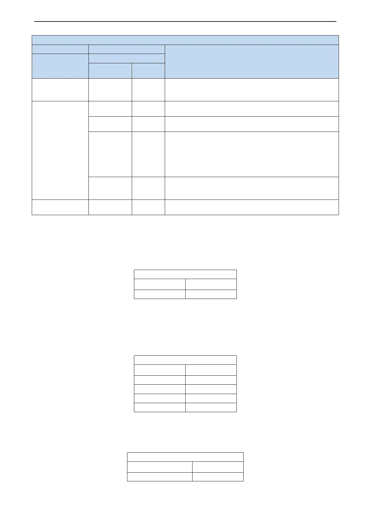
Description of each stage of debugging progress
Instruction for Code and Operating Method
Progress
LED
Display code
Display
08_ Preheat
confirmation of
08/oC
Display
repeatedly
After displaying for 2s circularly, the system will enter the next step
automatically.
09_ Confirmation of
valve of outdoor
unit
09/oF
Display
Standby status, ready to start.
09/on
Display
The system has started.
09/U6
Display
repeatedly
Malfunction shutdown.
The nixie tube of faulted module will display “09” and “U6”
repeatedly and the nixie tube of other modules will display “09” and
“J0”. In canse malfunction occurd, please check if the valve is
opened and if the connection pipes among different modules are
09/oC
Display
repeatedly
Confirmation of valve status.
All modules are halted normally, nixie tubes of all modules will
10_ Debugging
OFF ON Debugging is completed, the system is in standby status.
1.5 Function Setting(UMD400PH/A-M(P))
1.5.1 Function Setting of Outdoor Unit
After debugging, long press “SW1” button in master control for 5s, the system will enter function
standby status, main board indicator of outdoor unit is displayed acquiescently as follows:
LED
Function code Display method
Select corresponding function to switch LED function code through “SW1” and “SW2” button in
master control, function setting includes: outdoor quiet mode setting (A7), unit cooling and heating
function setting (A6), mandatory defrosting operation (n3) and energy conservation mode setting (n0).
After selecting corresponding function, short press “SW3” button for confirmation, main board
indicator of outdoor unit is displayed as follows:
LED
Function code Display method
A7 Blink
A6 Blink
n3 Blink
n0 Blink
1.5.2 Quiet Function of Outdoor Unit
This function applys to project with high requirements for noise of outdoor unit, after entering
function setting (A7), main board indicator of outdoor unit is displayed as follows:
LED
Function code Display method
,
,
 Loading...