3 OM-TDB (C,A,C2T™) & TDBC (C,A,C2T™) Domestic
For TDB units, attach the tilt handle (normally shipped inside the kettle) by carefully
threading it into the socket on the trunnion support. Be careful to avoid cross-
threading the fine threads on the trunnion. NOTE: After handle installation on the
right hand side, retain the hardware supplied with the unit for left hand installation.
INSTALLATION
WARNING: INSTALLATION OF THE KETTLE MUST BE DONE BY A CERTIFIED
ELECTRICIAN OR AUTHORIZED REPRESENTATIVE QUALIFIED TO WORK
WITH ELECTRICITY. IMPROPER INSTALLATION CAN RESULT IN INJURY TO
PERSONNEL AN/OR DAMAGE TO EQUIPMENT.
DANGER: ELECTRICALLY GROUND THE UNIT AT THE TERMINAL PROVIDED. FAILURE
TO GROUND UNIT COULD RESULT IN ELECTROCUTION AND DEATH.
CAUTION: BEFORE ANY ELECTRICAL CONVERSION, VERIFY THAT THE BRANCH
CIRCUIT WIRING IS ADEQUATE TO HANDLE ANY INCREASE AMPERAGE
REQUIREMENTS. REFER TO THE ELECTRICAL SPECIFICATIONS LISTED
BELOW.
Pull lead from 208V tab and insert on 240V tab.
The TDB/TDBC Kettle is provided with complete internal wiring and is ready for
immediate connection. Wiring diagrams are provided in this manual and on the
inside of the control housing service panel. Any mechanical or electrical changes
must be approved by Unified Brand’s Engineering Department.
The completed unit has been operated at the factory to test all controls and heater
elements.
1. Set the kettle in place and level it. The base should be securely fastened to a
table or work surface. Four 3/8”-16 N.C. threaded couplings are provided in
the base of unit. Installation under a ventilation hood is recommended.
2. Once the unit is anchored to a mounting surface, apply a small bead of silicone
caulk around the perimeter of the kettle base and seal the joint.
3. Core probe storage bracket (C2T models only)
a. It is recommend that the core probe storage bracket be installed on the
control console. It is not recommend that the core probe storage bracket
be installed on the kettle body or cover.
b. To obtain proper adhesion, the bonding surface must be unified, clean and
dry. Clean the bonding surface with rubbing alcohol and allow the surface
to dry. Next firmly apply pressure to the storage bracket to help improve
bond strength. After application, the bond strength will increase as the
adhesive flows onto the surface. At room temperature, approximately
50% of the ultimate strength will be achieved after 20 minutes, 90% after
24 hours and 100% after 72 hours.
4. Provide electrical power as specified on the electrical information plate
attached to the equipment. Observe local codes and/or The National Electrical
Code in accordance with ANSI/NFPA 70 - (current edition).
5. Standard equipment is shipped ready for 208V, 3-phase or 480V, 3-phase
operation. Refer to the wiring diagram located on the inside cover of the control
box and the instructions below for conversion to single-phase operation. A
jumper wire and “conversion” label are included with the unit. They can be
found in a plastic bag attached to the trunnion assembly inside the control box.
a. For conversion from 208V, 3-phase to 208V or 240V 1-phase or 480V,
3-phase to 480V, 1-phase:
i. Verify that the branch circuit wiring is adequate for any increased
amperage requirements (see table).
ii. For 240V 1-phase only, enlarge electrical inlet opening for 1” conduit
fitting. Use a 1” sealtite conduit fitting.
iii. Refer to wiring diagram for field conversion.
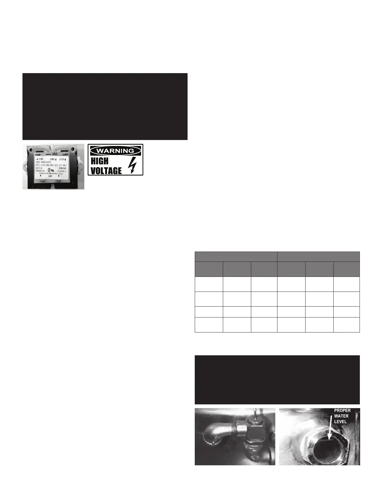
iv. For 240V 1-phase only, pull lead from 208V tab on control transformer
and insert on 240V tab (See photo).
v. Complete “conversion label” (supplied in bag) and adhere it to the
control box near the UL dataplate.
b. For conversion from 208V, 3-phase to 240V, 3-phase:
i. Verify that the branch circuit wiring is adequate for any increased
amperage requirements (see table).
ii. Pull lead from 208V tab on control transformer and insert on 240V tab.
(See photo)
iii. Complete “conversion label” (supplied in bag and adhere it to the
control box near the UL dataplate).
c. For conversion from 480V, 3-phase to 460V, 3-phase:
i. Verify that the branch circuit wiring is adequate for any increase
amperage requirements (see table below).
ii. Complete “conversion label” (supplied in bag and adhere it to the
control box near the UL dataplate).
6. Bring incoming electrical service through the conduit fitting (for 240V 1-phase,
a new one inch conduit fitting is required) at the rear of the support housing,
making a watertight connection with the incoming lines. A BX style connection
is not recommended.
7. Confirm that the jacket water level is at or just above mid point of sight glass
(new models). If the level is low, follow the instructions under “Jacket Filling
and Water Treatment” in the “Maintenance” section of the manual.
8. Ensure that the open end of the elbow on the outlet of the pressure relief valve
is directed downward.
TDB/TDBC SUPPLY WIRE REQUIREMENTS (THWN (75°) / THHN (90°) COPPER ONLY)
TDB/TDBC-20/24 (C,A,C2T) TDB/TDBC-40/48 (C,A,C2T)
VOLTAGE AMPS
SUPPLY
WIRE
VOLTAGE AMPS
SUPPLY
WIRE
208V 1 PH
3 PH
31
18
8
12
208V 1 PH
3 PH
52
30
6
8
240V 1 PH
3 PH
35
20
8
12
240V 1 PH
3 PH
60
35
4
8
460V 3 PH 7.3
14
460V 3 PH
14 12
480V 1 PH
3 PH
14
8
14
14
480V 1 PH
3 PH
25
15
10
12
INITIAL START-UP
IMPORTANT: BE SURE ALL OPERATORS READ, UNDERSTAND AND FOLLOW THE OPERATING
INSTRUCTIONS, CAUTIONS, AND SAFETY INSTRUCTIONS CONTAINED IN THIS
MANUAL.
WARNING: AVOID ALL DIRECT CONTACT WITH HOT SURFACES. DIRECT SKIN CONTACT
COULD RESULT IN SEVERE BURNS. AVOID ALL DIRECT CONTACT WITH HOT
FOOD OR WATER IN THE KETTLE. DIRECT CONTACT COULD RESULT IN SEVERE
BURNS.
The open end of the pressure relief valve
elbow must face downward.
Correct water level.
 Loading...