8 OM-TDB (C,A,C2T™) & TDBC (C,A,C2T™) Domestic
6. To remove burnt on foods, use a brush, sponge, cloth, plastic or rubber scraper,
or plastic wool with the cleaning solution. To reduce effort required in washing,
let the detergent solution sit in the kettle and soak into the residue. Do NOT use
abrasive materials or metal tools that might scratch the surface. Scratches
make the surface harder to clean and provide places for bacteria to grow.
Do NOT use steel wool, which may leave particles in the surface and cause
eventual corrosion and pitting.
7. The outside of the unit may be cleaned with a warm water (100°F or less)
spray. Do not use a high pressure spray.
8. The outside of the unit may be polished with a stainless steel cleaner such as
“Zepper” from Zep Manufacturing Co.
9. When equipment needs to be sanitized, use a solution equivalent to one that
supplies 200 parts per million available chlorine. Obtain advice on sanitizing
agents from your supplier of sanitizing products.
10. It is recommended that each piece of equipment be sanitized just before use.
11. Clean the kettle thoroughly. If there is difficulty removing mineral deposits or a
film left by hard water or food residues, then use a de-liming agent, following
manufacturer directions.
12. Rinse and drain the unit thoroughly before further use.
13. If cleaning problems persist, contact your cleaning product representative for
assistance. The supplier has a trained technical staff with laboratory facilities
to serve you.
CLEANING CORE PROBE
Remove all food soil from core probe by wiping entire core probe and cable
assembly with warm detergent solution and a clean cloth. Remove detergent
solution by wiping core probe and cable assembly with clean rinse water and a
cloth. Allow core probe and cable assembly to air dry. Do not immerse core probe.
Hand wash only and immediately let air dry.
MAINTENANCE
WARNING: AVOID ANY EXPOSURE TO THE STEAM BLOWING OUT OF THE PRESSURE
RELIEF VALVE. SEVERE BURNS CAN RESULT ON EXPOSED SKIN. FAILURE
TO CHECK PRESSURE RELIEF VALVE OPERATION PERIODICALLY COULD
RESULT IN PERSONAL INJURY AND/OR DAMAGE TO EQUIPMENT.
CAUTION: KEEP GREASE AWAY FROM ELECTRICAL PARTS LOCATED NEAR THE
GEARS.
WARNING: TO AVOID INJURY, READ AND FOLLOW ALL PRECAUTIONS STATED ON THE
LABEL OF THE WATER TREATMENT COMPOUND.
WARNING: USE OF ANY REPLACEMENT PARTS OTHER THAN THOSE SUPPLIED BY
THE MANUFACTURER OR THEIR AUTHORIZED DISTRIBUTORS CAN CAUSE
INJURY TO THE OPERATOR AND DAMAGE TO THE EQUIPMENT AND WILL
VOID ALL WARRANTIES.
CAUTION: INSURE ELECTRICAL POWER IS REMOVED AND THE GAS IS TURNED OFF AT
THE SHUTOFF VALVE PRIOR TO PERFORMING ANY MAINTENANCE ON THIS
KETTLE.
WARNING: THIS KETTLE IS DESIGNED TO BE WATER RESISTANT. FAILURE TO FOLLOW
PROPER MAINTENANCE PROCEDURES MAY VOID THE WARRANTY.
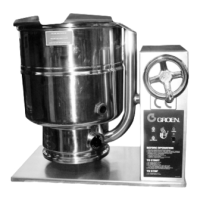
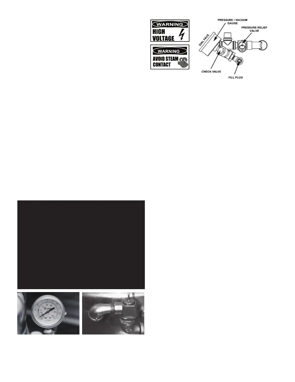
The pressure gauge should show a vacuum of 20 to
30 inches when the kettle is cold
The open end of the pressure relief valve
elbow must face downward.
The pressure relief valve and fill plug are located directly
behind the pressure/vacuum gauge.
PERIODIC MAINTENANCE
NOTICE: Contact an authorized representative when repairs are required.
A Maintenance & Service Log is provided at the back of this manual. Each time
maintenance is performed on your kettle, enter the date on which the work was
done, what was done, and who did it. Keep this manual on file and available
for operators to use. Periodic inspection will minimize equipment down time and
increase the efficiency of operation. The following points should be checked:
JACKET VACUUM/REMOVING AIR FROM JACKET
Every day, while the kettle is cold, read the pressure/ vacuum gauge. A positive
reading or a negative reading between zero and 20” vacuum on the pressure/
vacuum gauge indicates excess air in the jacket. Air in the jacket slows kettle
heating and can prevent the kettle from reaching operating temperature. To
remove air:
To remove air:
1. Start the unit. (See “Operation” section).
2. Make sure the elbow on the outlet of the pressure relief valve is turned so
that escaping steam is directed down toward the floor. Be sure and follow the
instructions on the attached pressure relief valve tag.
3. When the pressure/vacuum gauge reaches a positive pressure reading of 5
PSI, release trapped air by lifting the pressure relief valve ring for about one
second. Repeat this step, then let the valve ring snap closed, so the valve will
seat properly and not leak.
PRESSURE RELIEF VALVE
At least twice a month, test the pressure relief valve. Test the valve with the kettle
operating at 15 PSI (105 kPa), by holding the test ring for at least five seconds. Then
release the ring and permit the valve to snap shut. If the ring does not activate, if
there is no discharge, or if the valve leaks, stop using the kettle immediately and
contact a authorized service representative.
GREASE / LUBRICATION
1. Hand Tilt Models
At least twice a year, grease the two trunnion bearings. The bearings are
located within the kettle support housing. Remove the access panels from
the support housing with a screwdriver to gain access to the grease fittings.
Use a lithium-based, multi-purpose grease. When the access panels are
removed, the mounting bolts for the trunnion bearings and tilt switch can also
be checked for tightness. When finished, reassemble access panels to support
housing.
2. Crank Tilt Models
The gear housing has been fitted for proper lubrication of moving parts.
Since the gears do not run in oil, periodic lubrication with grease is essential.
Frequency of lubrication depends on operating conditions, but should occur
at least once every six months. The use of a Number Two grade LGI lithium
grease is recommended. Add grease through the Zerk fittings on the gear
housing until grease flows out of the bearings around the trunnion shaft. Place
a liberal amount of grease on the gear to cover the arc that is in contact with
the worm gear.
 Loading...