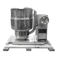
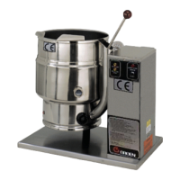
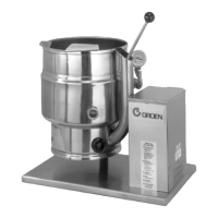
3 OM-TDH(C)-20/24/40/48 (C,A,C2T™) Domestic
INSTALLATION
WARNING: THE UNIT MUST BE INSTALLED BY PERSONNEL WHO ARE QUALIFIED TO
WORK WITH GAS, ELECTRICITY AND PLUMBING. IMPROPER INSTALLATION
CAN CAUSE INJURY TO PERSONNEL AND/OR DAMAGE TO THE EQUIPMENT.
THE UNIT MUST BE INSTALLED IN ACCORDANCE WITH APPLICABLE CODES.
THE UNIT MUST BE INSTALLED BY A LICENSED PLUMBER OR GAS FITTER
WHEN INSTALLED WITHIN THE COMMONWEALTH OF MASSACHUSETTS.
DANGER: ELECTRICALLY GROUND THE UNIT AT THE TERMINAL PROVIDED. FAILURE
TO GROUND UNIT COULD RESULT IN ELECTROCUTION AND DEATH.
WARNING: THIS UNIT IS FOR COMMERCIAL USE. DO NOT USE HOME OR RESIDENTIAL
GRADE GAS CONNECTIONS. THEY DO NOT MEET GAS CODES AND COULD
BE HAZARDOUS.
For efficient performance the kettle must be installed in a well-ventilated
area. Items which might restrict or obstruct the flow of air for combustion and
ventilation must be removed. The area directly around the appliance must be free
of combustible materials.
1. Installation can be on a combustible or noncombustible floor. Clearances
should be per table below.
MINIMUM CLEARANCE FROM
COMBUSTIBLE WALLS
RECOMMENDED
CLEARANCES
Left Side 1 in. 1 in.
Right Side 0 in. 12-16 in. for servicing
Rear 1 in. 3 in. for faucet bracket
2. We recommends installation of the unit under a vent hood. The base must be
fastened to a working surface or stand.
3. Complete the piping to the gas service main using ½ inch IPS pipe or an
approved equivalent.
4. Provide 115 VAC, 60 cycle, 1 phase, 1 AMP electric service. Local codes and/
or The National Electrical Code should be observed in accordance with ANSI/
NFPA-70 latest edition. AN ELECTRICAL GROUND IS REQUIRED. The electrical
schematic is located on the inside of the service panel and in this manual.
5. Electrical connection to the unit must be water resistant sealtite conduit type
or equal and utilize the water resistant conduit fitting provided on the unit.
6. The installation must conform with local codes or the American National
Standards Z223.1 - latest edition National Fuel Gas Code. The kettle should
be installed in an adequately ventilated room with provision for adequate air
supply. The best ventilation will employ a vent hood and exhaust fan with no
direct connection between the vent duct and the kettle flue. DO NOT obstruct
the flue or vent duct after installation.
7. Core probe storage bracket (C2T models only)
a. It is recommend that the core probe storage bracket be installed on the
control console. It is not recommend that the core probe storage bracket
be installed on the kettle body or cover.
b. To obtain proper adhesion, the bonding surface must be unified, clean and
dry. Clean the bonding surface with rubbing alcohol and allow the surface
to dry. Next firmly apply pressure to the storage bracket to help improve
bond strength. After application, the bond strength will increase as the
adhesive flows onto the surface. At room temperature, approximately
50% of the ultimate strength will be achieved after 20 minutes, 90% after
24 hours and 100% after 72 hours.
8. PRESSURE TEST WARNING
a. Test pressure exceeding ½ PSIG (3.45 kPa). During pressure testing of the
gas supply piping system at pressures exceeding ½ PSIG, the appliance
and its individual shutoff valve must be disconnected from the gas supply
piping system.
b. Test pressure equal to or less than ½ PSIG (3.45 kPa). During pressure
testing of the gas supply piping system at pressures equal to or less than
½ PSIG, the kettle must be isolated from the gas supply piping system by
closing its individual manual shutoff valve.
9. Adequate space for proper servicing and operation is required. DO NOT block
any air intake spacings to the combustion chamber or obstruct air flow.
10. After the kettle has been connected to the gas supply, check all gas joints for
leaks. A soap solution or other suitable gas leak detector should be used. Do
not use flame when checking for leaks.
11. Once the unit is anchored to a mounting surface, apply a small bead of silicone
caulk around the perimeter of the kettle base and seal the joint.
12. Make sure the water level is correct in the jacket, by confirming that the
level is near the middle of the sight glass. If the water level is low, follow the
instructions in Jacket Filling and Water Treatment in the Maintenance section
of this manual.
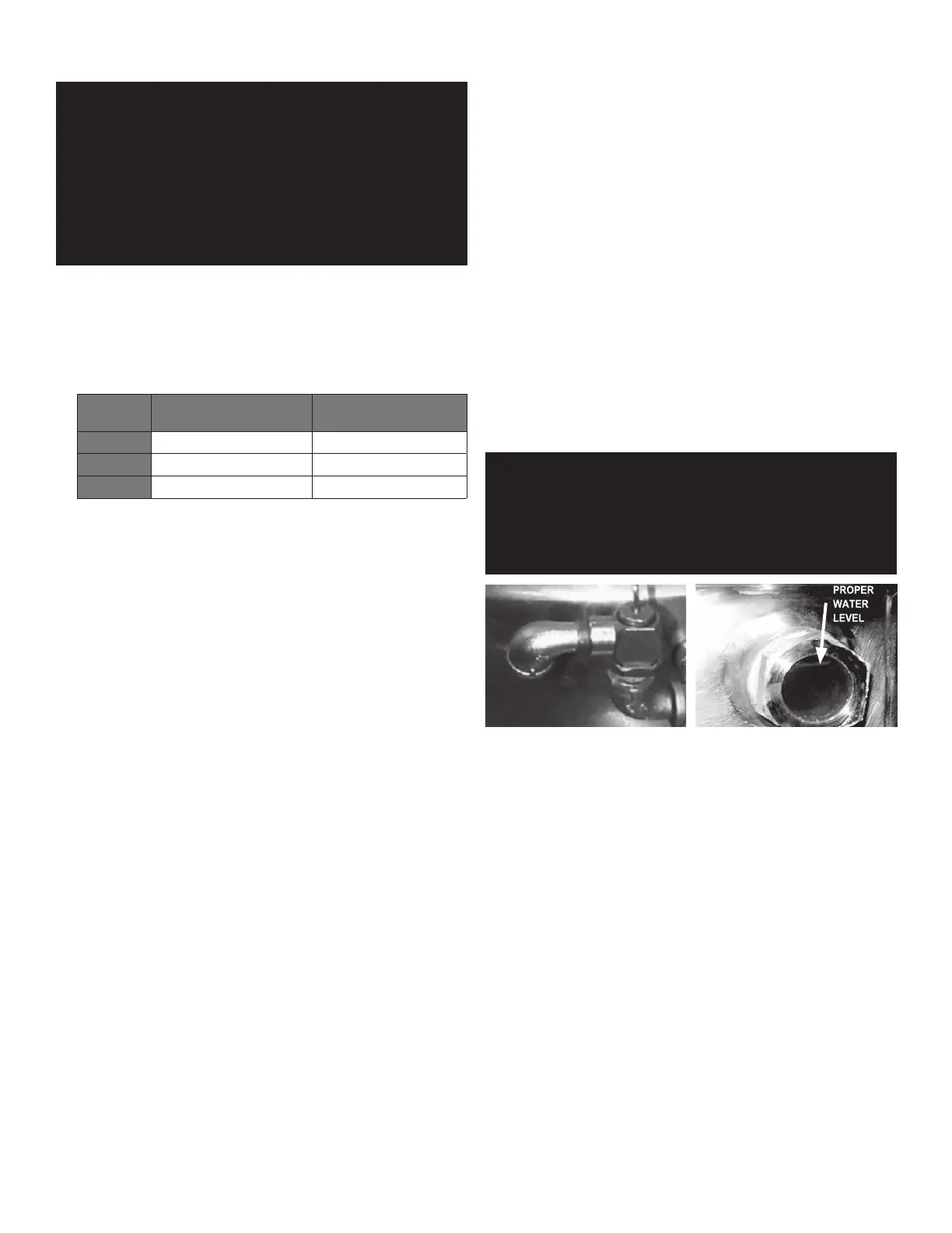
13. Check to be sure that the open end of the elbow on the outlet of the pressure
relief valve is directed downward. Be sure to read and follow the instructions
on the attached pressure relief valve tag.
INITIAL START-UP
IMPORTANT: BE SURE ALL OPERATORS READ, UNDERSTAND AND FOLLOW THE OPERATING
INSTRUCTIONS, CAUTIONS, AND SAFETY INSTRUCTIONS CONTAINED IN THIS
MANUAL.
WARNING: DO NOT STAND ON OR APPLY UNNECESSARY WEIGHT OR PRESSURE ON THE
KETTLE FRONT OR POURING LIP. THIS COULD RESULT IN THE OVERLOAD AND
FAILURE OF THE TILT MECHANISM, AND POSSIBLE SERIOUS INJURY AND
BURNS TO THE OPERATOR AND OTHERS.
The open end of the pressure relief valve
elbow must face downward.
Correct water level.
After the kettle has been installed, the installer should test to ensure that it is
operating correctly.
1. Remove literature and packing materials from inside and outside of the unit.
2. Add water to the kettle to a depth of at least one inch.
3. Make sure the supplies of gas and electric power are on.
4. Follow the “To Start Kettle Heating” instructions in the Operation section of
this manual. Begin heating the water at the highest thermostat setting. The
indicator light should come on and heating should continue until the water
boils.
5. To turn off the unit, follow “To Stop Kettle Heating” in the Operation Section of
this manual.
If the kettle functions as described, it is ready for use. If the unit does not operate
as designed, contact an authorized Service Agent.
 Loading...