Electrical Connection
16
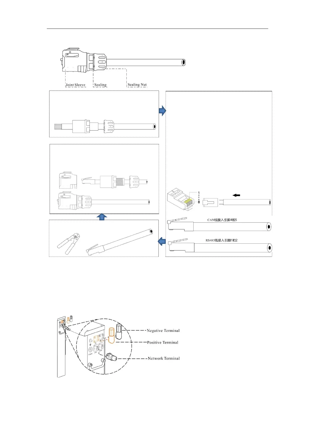
Step 3 Make network cables.
1. Strip cable sheaths for 15±0.5mm first.
Insert sealing and sealing nut along the
cable.
2. Network cable adopts standard 8-core
cable. Reserve two wires, cut the other
six wires.
Make CAN network cable: insert the two
remaining wires into pin 4 and pin 5 of RJ45
plug. Ensure the two wires stay aligned and
keep consistent between wire color and pin.
Make RS485 network cable: insert the two
remaining wires into pin 1 and pin 2 of RJ45
plug. Ensure the two wires stay aligned and
keep consistent between wire color and pin.
3. Crimp the RJ45 plug with a wire crimper.
4. Connect RJ45 plug with joint sleeve, and
tighten up sealing, sealing nut and joint
sleeve.
Step 4 Insert power cables and network cable into battery terminals.
1. Measure battery voltage with a multi-meter and ensure the voltage output is 0V under power-off mode.
2. Plug one end of the power cables that have been made in Section 4.2 step 2 into DC breaker, and plug the
other end into the battery terminals.
3. Plug the CAN network cable that has been made in Section 4.2 step 3 into a network terminal of battery
(CMO1 or COM2), and plug the other end of CAN network cable into network port of PCS.
 Loading...