Figure 30
3 Contact
If you have some requirements or problems concerning ShineVision, please
contact us and provide related information.
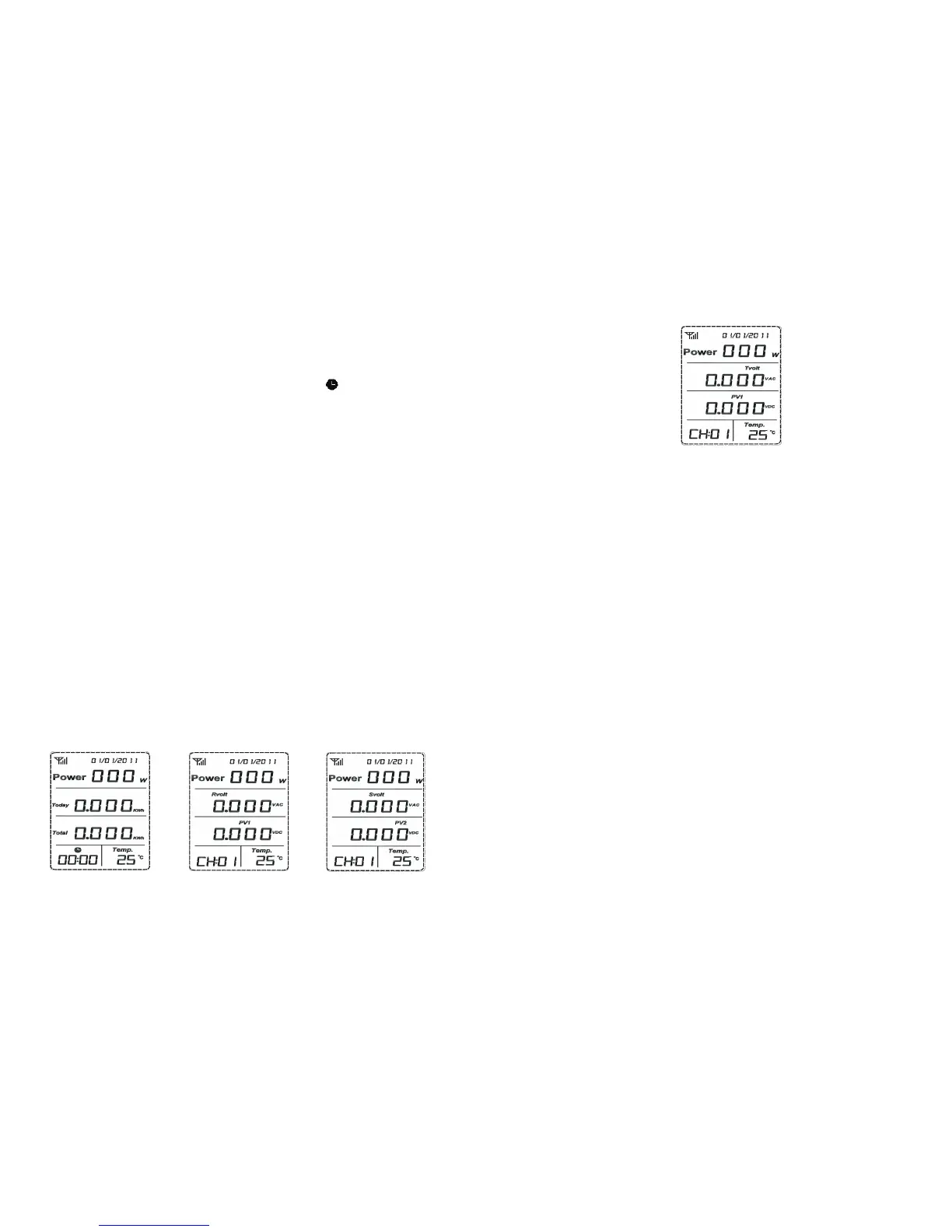
2.7 Reading of Data of Emitter No.1 to 6
Press “Up” or “Down” for a short while in the default interface, then “CH:01” or
“CH:06” will be displayed in the clock area, the clock symbol will disappear and
LCD will show the data of the current channel (The following figures show relelevant
display under relevant codes by switching 6 sensor channels in the default interface).
In the default interface, the total data for Channel 1 to 6 are displayed, as shown in
Figure 27. The LCD display is shown as Figure 28 to 30 after entering all channels
(The figures show the data of CH:01 channel; the data of other channels are much
similar and the only difference is that clock areas show relevant channel numbers).
The explanations on LCD display are as follows:
The first line shows the real-time power of photovoltaic inverters for each
channel.
The second line shows phase voltage for three-phase AC of each channel.
The third line shows two-circuit PV voltage for each channel.
The fourth line shows time and real-time temperature under the current
environment.
1.
2.
3.
4.
Notes: When choosing CH:01 to CH:06, press “OK” for a short while for the enquiry
of “Rvolt--- PV1”, “Svolt--- PV2” and “Tvolt--- PV1” for relevant channel and the
clock area will display relevant channel number.
Figure 27 Figure 28 Figure 29
 Loading...