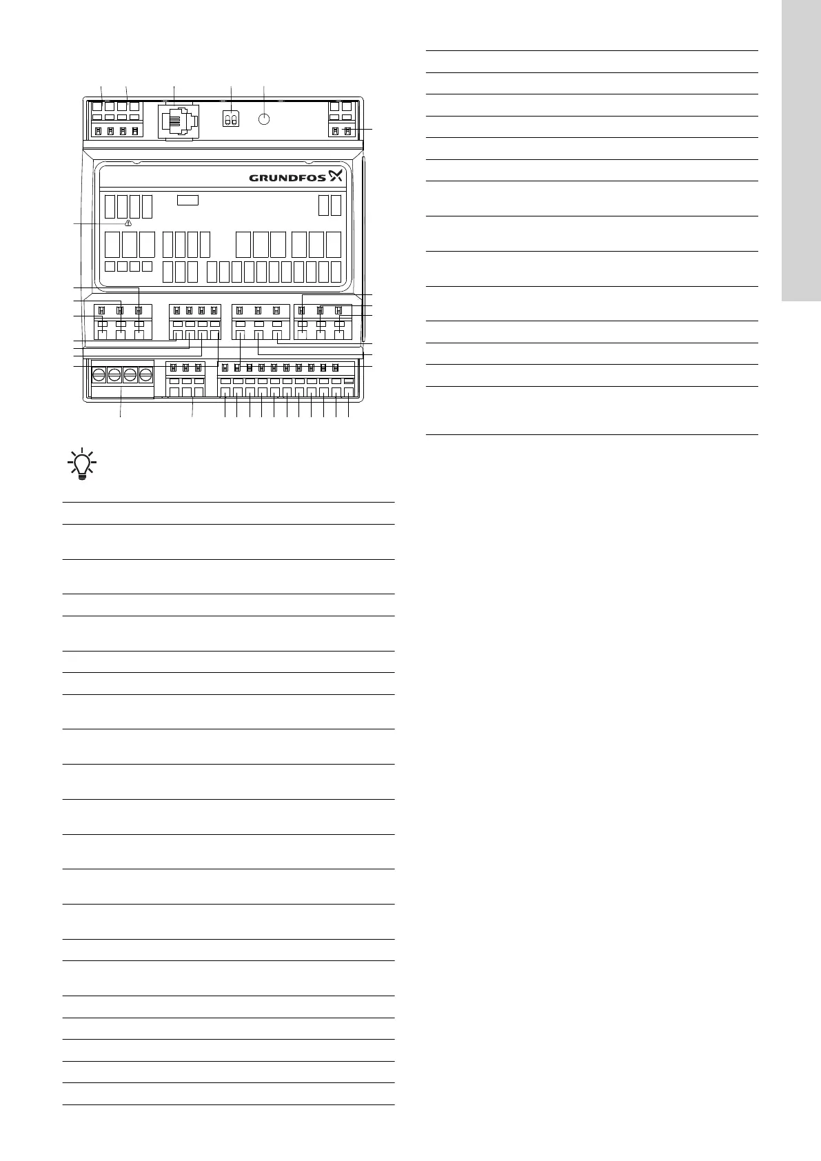
3.3 Terminals
26
27
28
29
30
31
32
7
6
8
9
10
11
12
23 2225 24
21 20 19 18 17 16 15 14 13
1
2 3
4
5
Max. 2A Max. 2A
24 V
GND
REL 4C
GND
DI 4
GND
GND
GND
MPF2
MPF1
GND
DI 3
DI 2
DI 1
GND
24 V
EXT
ADI
REL 3C
PTC 2B
PTC 2A
PTC 1A
REL 2
COM
REL 1
L1
L2
L3
N
PTC 1B
CT 2B
CT 2A
CT 1A
CT 1B
REL 4O
REL 3O
REL 3
REL 4
GENI
480Y / 277V
AC
IO 242
33
12
TM072017
Remember to separate potentially low-voltage cables from
potentially high-voltage cables when connecting them to
the control unit.
Pos. Description
1
Current transformer, pump 1.
Optional
2
Current transformer, pump 2.
Optional
3 GENIbus
4
Switch for termination resistor,
SW1
5 Not for use
6 Supply voltage, 24 VDC
7
User-configurable output relay
4, normally closed
8
User-configurable output relay
4, common
9
User-configurable output relay
4, normally open
10
User-configurable output relay
3, normally open
11
User-configurable output relay
3, common
12
User-configurable output relay
3, normally closed
13
Supply voltage for sensors, 24
VDC, max. 50 mA
14 Ground, GND
15
User-configurable analog or
digital input
16 Ground, GND
17 Digital input 4
18 Ground, GND
19 Digital input 3
20 Ground, GND
Pos. Description
21 Digital input 2
22 Ground, GND
23 Digital input 1
24 Motor-protection feedback
25 Phase monitoring
26
Temperature or moisture sensor
input, pump 1
27
Temperature or moisture sensor
input, pump 1
28
Temperature or moisture sensor
input, pump 2
29
Temperature or moisture sensor
input, pump 2
30 Relay output, pump 1
31 Common
32 Relay output, pump 2
33
Caution, only dedicated current
transformers are to be
connected to these terminals.
Related information
2.3.1 Connecting the power supply
7
English (GB)
 Loading...