3.6 PTC
The control unit offers a thermal protection, PTC, for the connected
motors.
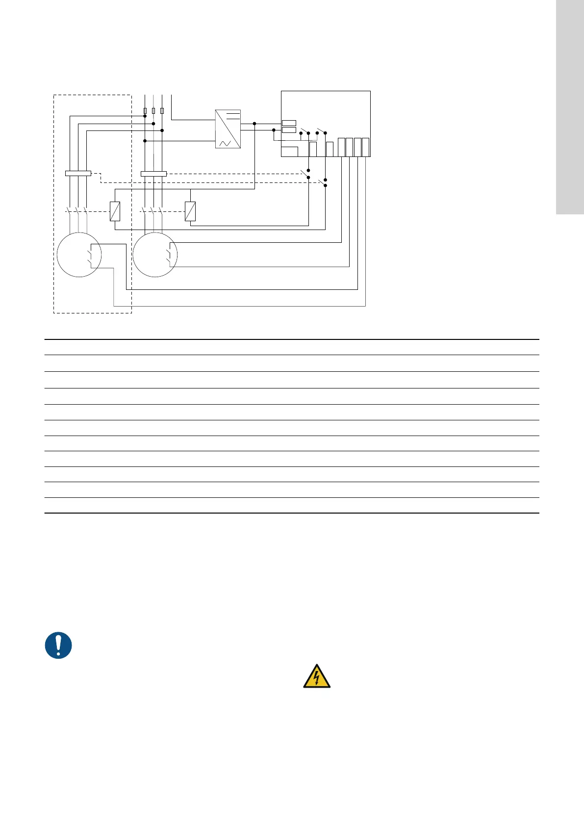
IO 242 is a subassembly ensuring safe stop of the motors. The PTC
function fulfills performance level C, category 1, according to ISO
13849. The drawing shows the recommended PTC wiring for IO
242.
1 2 3
5
MM
24 V
GND
COM
PTC 1A
PTC 1B
PTC 2A
PTC 2B
REL 1
REL 2
MM
IO 242
4
6
7
7
9
9
8
8
TM075363
Pos. Description
1
L
1
2
L
2
3
L
3
4 N
5 Power supply
6 IO 242
7 Motor relay
8 Motor protection
9 PTC
M Motor
Related information
2.3.1 Connecting the power supply
5. Technical data
4. Servicing the product
The module cannot be serviced.
• Contact Grundfos. If the module is faulty, it must be replaced
4.1 Inspecting the product functions
You must perform an inspection every fifth year to ensure
full functionality of the product.
Recommended inspection procedure:
1. Ensure that the motor is allowed to start, i.e. the motor is cold
and there is enough water in the pit.
2. With the PTC sensors connected, start the motor and observe
that it runs.
3. Disconnect power from the panel.
4. Disconnect the PTC sensors from IO 242.
5. Reconnect power to the panel.
6. Attempt to start the motor and observe that it does not start,
and ensure that an alarm for high motor temperature is
present.
7. Disconnect power from the panel, and reconnect the PTC
sensors to IO 242.
8. Perform a visual inspection to ensure that the PTC wiring is
correct.
9. Reconnect power to the panel.
4.2 Replacing the IO module
WARNING
Electric shock
Death or serious personal injury
‐ Switch off the power supply before making any
electrical connections.
‐ Make sure that the power supply cannot be switched
on accidentally.
1. Switch off the power supply to the product and
other components with external supply.
2. Write down the terminal connection of each wire to ensure
correct reconnection.
3. Disconnect all wires.
4. Press the module up gently (1).
9
English (GB)

 Loading...